Organization of surface water flow - everything for MGSU - educational portal for students. Construction of a surface water drainage system Drainage of groundwater and storm water
The drainage system for rain or melt water from buildings (drainage) is one of the most important for maintaining buildings of any purpose in good condition and extending their service life. The accumulation of water in a place not intended for this purpose can easily lead to the destruction of the foundation and surrounding area, contamination of the facade coating, death of plants, and waterlogging of the area.
One of the options for protecting a building is its waterproofing, but this alone is not enough for complete protection. A joint barrier to moisture from waterproofing and a drainage system will be effective.
In some cases, a system that will drain water away from the house is mandatory. For example, in houses that are located in lowlands or on clay and loamy soils. The risk of destruction of building foundations is also high in areas with high precipitation levels and high groundwater levels. In addition to natural causes, there are also man-made threats - buildings with a buried foundation are susceptible to water accumulation near it, and concrete or asphalt paths prevent water from seeping into the soil.
A system that includes roofing, surface and drainage precipitation collection is considered to be complete.
The roof water collection system consists of gutters along the edge of the roof, vertical pipes, usually located at the corners of buildings and outlet funnels. Round drainage systems are installed on multi-storey buildings residential buildings or industrial buildings, since they have greater throughput.
Pipes with rectangular cross-section installed on small buildings. The material for the production of pipes is usually plastic or galvanized metal - durable, practical and lightweight. When installing roofing system It is important to firmly strengthen all elements to avoid noise during the passage of water.
The type of roof also matters – pitched or flat. If pitched roof does not require additional devices, then for a flat roof, as well as open balconies and terraces, it may be necessary to install an internal drainage system.
Surface system does not require large volume earthworks: rain trays are laid in shallow trenches and covered with protective gratings. Experts calculate the location of the water collection point, the size of the trays and the number of trenches, taking into account the terrain and the average amount of precipitation in the area.
 Deep drainage is the most common option for arranging a stormwater management system. Requires a large amount of excavation work - trenches should be about 80 cm deep. Perforated pipes are laid in trenches on a layer of crushed stone and durable geosynthetic fabric. Please note that the use of geosynthetic fabric is recommended when installing in clay or loamy soil. Laying in sandy soil does not need such a canvas.
 This drainage system is especially important for buildings that have a basement, ground floor at high groundwater levels. Although rainwater will only be collected by this drainage system during the rainy season (spring and fall), its absence can cause serious damage to the foundation and surrounding area.
In addition to the above-mentioned drainage systems, there are several less common ones, for example, backfill drainage or reservoir drainage.
Formative drainage is used for apartment buildings, underground passages and industrial complexes. The backfill drainage system is used in small areas where it is difficult or impossible to install open drainage. Before arranging it, you should know that subsequent inspection of earthen trenches and their maintenance will be impossible, since after laying the geotextile, crushed stone and pipes in the trench, everything is covered with a layer of turf for a more attractive appearance.
Options for taming rainwater
Some types of drainage have options that can be selected depending on the amount of rainfall and installation methods.
The surface drainage system has linear and point types. The linear view involves collecting rainwater from the entire local area. The system is formed by lines of trenches through which water flows into the storage tank.
 The point system is engaged in collecting water at certain points on the site, most often these are outlet funnels of drains or watering taps. Collection points are covered with grates to prevent branches, leaves and other debris from entering the drainage system. The drainage pipes of the point system are connected to the main pipe, which leads to the well.
 There is also a combination of point and linear views, which is considered the most profitable in terms of costs and operation.
Based on the installation method, drainage systems are divided into open and closed.
Open systems are a connection of shallow inclined trenches united by a common drainage ditch. Plastic or concrete trays covered with gratings are placed in the trenches. This type of drainage is preferred due to its low cost and speed of installation.
It is best to carry out the arrangement of drainage during the construction of the building, installation after completion construction work is associated with certain difficulties. In the period between the installation of a full-fledged system, you can organize temporary drainage - collect water manually, using barrels: under drainpipe a container of suitable volume is installed.
A closed system has a narrower and shallower trench, which means less throughput. The “advantages” are considered to be a more aesthetic appearance and safety of operation.
Vertical drainage can be called an option deep system drainage. Installed near buildings required quantity wells with submersible pumps. This drainage option is the most effective, but also the most expensive, since it requires a large amount of excavation work and special knowledge.
Also, a closed installation of a drainage system can be divided into continuous and wall-mounted. As the name implies, a continuous one is installed throughout the entire site, while protecting the base and surrounding area.
 The wall system is located exclusively near the foundation of the building, protecting only the structure from rainwater.
 Preparing for installation of a system for draining excess water from the house
Before starting work on arranging a drainage system, it is necessary to prepare information on the topography of the given territory, soil composition, and average precipitation. This data can be taken from specialized services. Vibration loads in the area where pipes will be laid must be known to the customer himself; a specialist from a specialized construction company will help to determine them correctly.
Rainwater discharge location
No less important element system is a rainwater collection point. They can serve as a natural reservoir, a specially prepared drainage field consisting of a number of depressions through which water seeps into the soil, or sewer collectors. The main condition for arranging a discharge site is its location at the lowest point of the site. In areas with flat terrain, a drainage well with a pump is installed.
A well can also be accumulative: the water is then used for irrigation, and absorbent: in the absence of a bottom, water slowly seeps into the ground.
Under no circumstances should you install a water collection point near the foundation of the house, and you should also not use underground drainage with surface drainage. This may result in flooding of the building.
It is possible to choose the optimal type of drainage system only after a detailed study of the characteristics of the territory, weather reports for the area, the method of using the local area, and the purpose of the building itself. Will be able to take into account and correctly use all information experienced specialist, therefore, this complex and responsible work should be entrusted to a construction company with extensive experience in installing various types of drainage.
Errors or even inaccuracies in the work carried out to drain rainwater can lead to irreparable consequences. On the contrary, compliance with the requirements and rules will extend the life of the building by more than half a century, eliminating unnecessary expenses and hassle.
Let's be honest: most of us would not want to have a plot of land with a large slope. This is understandable - the unknown is scary. Let's sort everything out together and then draw conclusions.
Opportunities and disadvantages of a site with a slope
First of all, let's consider possible troubles:
- the choice of location of both the house itself and buildings is noticeably limited;
- there are problems with watering, since water will not remain in the soil for long;
- movement around the territory is complicated, especially in icy conditions;
- it is difficult to organize sufficient space for games and entertainment;
- the need to combat landslides and soil erosion;
- a steep slope is a source of increased danger for children;
- poor orientation of the slope of the site relative to the sun can lead to either excessive or insufficient illumination of the earth's surface;
- the movement of air masses along the slope can lead to drying out of the soil at the top and frosts at the bottom of the slope;
- improvement of the site with large slope requires increased costs;
- difficulties with access roads are likely;
- securing water can be challenging.
Now about positive aspects placing a house on a slope:
- you will get a building plot at a lower price, and the increased costs of its arrangement can be partially offset by your own creative work;
- water drainage problems can be easily solved: the yard area will be dry, it will be possible to arrange the basement floor of the house or a cellar;
- problems with groundwater on such lands are a rare occurrence;
- the hillside always protects the house from the wind from one direction;
- the cost of constructing the basement floor of a building is noticeably reduced, since the entire excess volume of land is easily used to partially level the terrain;
- the windows of the house, located high, offer a wide view;
- when placing the site on the south side of the slope, the insolation of the courtyard can be increased, on the contrary, if the site is located on the north side, solar Activity will be weakened;
- an area located on an eastern or western slope will have average illumination;
- apparently the most important thing: the use of a huge list of landscape design techniques (retaining walls, terraces on the slope of the site, alpine slides, winding paths, a pond, a dry stream, special ornamental plants, etc.) will allow you to obtain a natural, organic and unique design of the plot of land.
As you can see, the pros and cons gradually flow into tastes and preferences. The following video examines some of the features of planning a site with a slope.
Thus, by spending more effort and money on developing a site with a slope, you get a more interesting and unusual result.
Of course, the degree of significance of the above circumstances is directly related to the magnitude of the difference in ground level. To calculate it, you need to divide the difference in heights of the extreme points of the site by the distance between them and convert the result into percentages. For example, if the maximum height difference is 3.6m, and the distance between the difference points is 20m, then the slope will be 3.6: 20 = 0.19, that is, 19%.
It is believed that a slope of up to 3% is flat terrain, but a site on a steep slope of more than 20% is not suitable for construction.
Features of placing buildings on a slope

 Development plan for a site on a slope
 Firstly, it should be noted that the underground and basement parts of a house on a site with a slope will inevitably have characteristic features. This also applies to other buildings. Usually the house is located on the highest and driest place. Thus, the issue of drainage from the main facility is resolved. The toilet, compost pit, shower should be located below the house and no closer than 15-20m. Recreation area - gazebo, barbecue, etc. It is better to do it on the same level as the house. It is better to place buildings between which the most frequent movement is expected on different sides of the site. In this case, the length of the paths increases, but the slope to be overcome decreases. In the idealistic version, buildings are placed in a checkerboard pattern. The garage is conveniently located at the bottom of the plot. In this case, the garage building can be used as a means of compensating for the steepness of the slope.
Strengthening terraces on a sloped area
There are two fundamentally different methods for planning an uneven plot: without changing the landscape or with maximum leveling of the ground surface. In my opinion, a compromise version of all possible methods of leveling the territory, as well as masking differences in ground level, should be used.
In this case, there is no point in achieving complete leveling of the site.
When planning an inclined surface, several tasks are set: preventing soil sliding; ease of use of the earth's surface for recreation and cultivation of fruit crops; ease of movement around the compound. First of all, the relief is leveled as much as possible by moving the soil. It is quite possible that it would be profitable to remove part of the land from the plot or, on the contrary, to bring in the missing soil. A reasonable technique is to use the land obtained by digging a pit for a basement or cellar.  Creating terraces using stones
The second, most common method is terracing, that is, creating flat areas located on different heights. The more terraces, the smaller their height, and, therefore, the simpler the arrangement of the slope. With a terrace height of up to 70 cm, it is possible to create retaining walls. The best material- natural stone. For such a design, you need to make a base of crushed stone 10-20 cm high. If the terrace height is small, the stone can be laid without a binder material. However, in such a situation, there is a danger of soil being washed away by water during rain or irrigation. It is safer to lay the retaining wall on cement mortar. The use of brick to create terraces is considered inappropriate, since repeated exposure to moisture and low temperatures leads to its rather rapid destruction.
Suitable for terrace heights up to 2 meters reinforced concrete structures: foundation blocks, slabs and monolithic concrete. It often makes sense to create concrete retaining walls with some slope, taking into account the squeezing effect of the soil. In difficult situations, you cannot do without a reliable and complete foundation. There is no point in additionally finishing retaining walls with decorative tiles or stones on an adhesive or cement base. Frost and water will quickly ruin your work.

 Concrete retaining wall
 Structurally, “ventilated facades” are suitable here. However, in a decorative sense, such a technique is hardly appropriate. It is much easier and more efficient to place a corrugated surface with a special pattern into the concrete formwork. Subsequently, you can decorate the concrete with durable water-based paints.
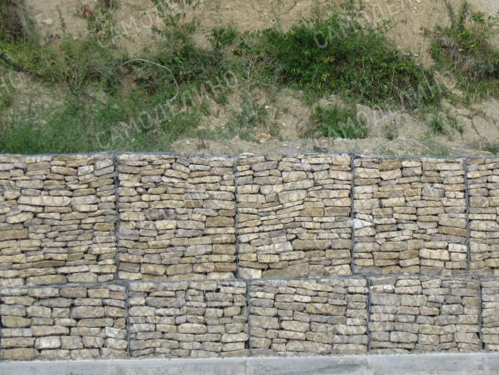
It is very effective to use a French invention - gabions - to strengthen terraces. Gabions are rectangular mesh structures filled with natural stone. You can purchase ready-made modules from special durable wire or make it yourself. Gabions are not afraid of soil erosion, as they do not have absolute rigidity. They are also resistant to water, as they do not retain it. When filling gabions with stone and crushed stone, you can add a certain amount of earth, in this case greenery will soon sprout, which will disguise the wire and give the retaining wall a natural look. natural look.
The simplest method of strengthening a slope is an inclined embankment. It is better to strengthen the embankment from crumbling plastic mesh and geogrid. Being planted with a lawn, special grass and shrubs, such an embankment surface will be quite reliable and aesthetically pleasing.
 Gabion retaining wall
 Water disposal - two sides of the coin
It’s good that in an area with a slope, the water will run away quite quickly in both rain and flood: it will be dry underfoot. However, quickly receding water can take with it a noticeable part of the soil and destroy something. The conclusion is clear: you need to think about how to properly make drainage on an area with a slope.
The optimal scheme seems to be when water is collected from different areas by separate conduits extending outside the yard. Moreover, each terrace should ideally be equipped with a drainage system.
The simplest solution is to lay open concrete trays. The trays are laid on a pre-prepared base: a layer of crushed stone about 10 cm, cement-sand mixture(in a ratio of 1 to 10) about 5 cm. The trays can be easily cut and adjusted to each other with using an angle grinder. Relatively cheap trays have disadvantages: they interfere with pedestrian paths and their cross-section is insufficient when placed on common drains in the lower part of the site. The last obstacle can be overcome by making drainage channels yourself from concrete. Pipe sections can be used to form channels suitable diameter. There are also closed-type storm drain options that are manufactured by industry. Top part Such drains are closed with special gratings to receive water. Such structures look aesthetically pleasing and do not create obstacles for the movement of people. However, they are noticeably more expensive and more difficult to install. In addition, the problem of insufficient cross-section in the lower part of the steep section remains relevant.
 Drainage using trays
 Another option for drainage is drainage channels. The system is closed and saves space. To organize drainage, trenches with a depth of 0.3-1 m are opened. The bottom of the trench is covered with sand; a layer of 10 cm is sufficient; it must be compacted. The sand is covered with geotextile, on top of which medium-sized crushed stone is poured. The thickness of the crushed stone layer is up to 20 cm. If a small flow of water is expected in this area, then it is enough to cover the crushed stone again with geotextiles, and then successively fill it with sand and soil. If the water flow is high, a perforated plastic pipe is additionally laid in the channel. The rules for laying pipes are the same as for installing sewer systems: slope of at least 3%; fewer turns and sudden changes in level to prevent accumulation of debris in problem areas; reliable pipe connection.
Paths and stairs - decoration of the site
It is clear that traveling over uneven terrain can be difficult and even dangerous. Hence the requirement to approach the arrangement of all routes for people’s movement with special care. Please note that even a relatively flat path with a slope of about 5% can become an insurmountable obstacle during icy conditions. This means that the coating of all paths and stairs should be as rough and ribbed as possible. The steps of the stairs should correspond as closely as possible optimal sizes: tread width 29cm, riser height 17cm. The slope of the stairs cannot exceed 45%. It is better to avoid flights of more than 18 steps and provide rest areas.

 Staircase made of stone
 It is very convenient if the height of the steps of all stairs is the same. This is quite real. For example, during construction own home With our own hands, we managed to ensure the same parameters for the steps on both floors of the house, including the basement, as well as on the porch and in the garage. The provision of handrails on steep slopes is absolutely necessary, and even on quite flat sections handrails will be fully justified.
Materials for arranging paths and stairs can be very different: crushed stone, stone, concrete, wood, artificial turf and plastic gratings. Stairs, separate steps, winding paths - all these attributes should be considered as elements of decoration and individualization of the yard area. At the same time, I consider it necessary to remind General requirements: Travel paths should not become slippery or dangerous during inclement weather. It may be necessary to provide special handrails for children.
Wonderful landscaping and landscaping opportunities
Alpine landscape design on a site with a slope can be called a pleasant necessity. It is based on natural stones, flowers and other plants. All this together and in various applications serves to counteract soil erosion on the slope and at the same time serve as decoration. Since water does not retain water well on a slope, plants may require frequent watering. Thus, for vegetable garden beds and fruit trees It is necessary to select the best areas: well-lit, protected from the wind. Sloping beds located at the base of the slope may be exposed to accumulated cold air.

 Strengthening the slope with plants
 Ideally, the entire area should be planted with various plants. On slopes, unpretentious creeping plants, which do not require a lot of moisture and have a branched root system. Different climatic regions may have their own preferences. Concerning middle zone Russia, then the use of shrubs is appropriate here: ivy, barberry, lilac, Japanese quince, elderberry, turf, etc. Coniferous plants will wonderfully decorate the site: juniper, spruce, cedar, pine. Deciduous trees are well suited: birch, hazel, willow (in damp places). For arranging a rock garden, tenacious plants, sedums, cinquefoils, bells, alpine carnations, sedums, etc. are well suited. It is quite appropriate to arrange areas of the lawn.
In order to visually level the terrain, tall plants are planted at the bottom of the slope. Sometimes it becomes necessary to block buildings located at the top of a slope from view, and then the strategy for placing tall and low-growing varieties is changing.
A low fence along the retaining wall will cover unsightly surfaces and beautify the landscape. It is extremely appropriate to create a rock garden on a site with a slope. To do this, stones are laid out on the slope different sizes and in no particular order. Interesting use of stones different composition and textures. Free areas are filled with crushed stone, marble chips, etc. The spaces between the stones are planted with the plants described above. Thus, with your own hands you can create the most unusual and amazing creative compositions. Of course, plants will grow only on soil that is quite suitable for this.
You can decorate your mountain garden with figurines made by yourself or purchased at a store for summer residents.

 Stream bed made of stones
 Landscape composition“dry stream” was invented in Japan almost specifically for sloped surfaces. The idea is to simulate water using small stones and/or plants. At the site of the future channel, it is necessary to dig a shallow trench of the intended shape of the stream. The bottom of the groove is covered with geotextile to protect against weeds. Then drainage is laid in the form of small crushed stone, and the bed is covered with soil on top. The “stream” is planted with blue and blue flowers or filled with any crushed stone, preferably blue. Then you can plant flowers along the “shores”. A “dry stream” can exist on its own, or originate from a clay jug partially buried in the ground. It would be interesting if the path passing nearby would “throw” a small bridge over the “stream”.
On a site with a slope, it is very interesting to use the following technique: a channel for draining water is designed in the form of a “dry stream” made of stones. When it rains, the stream will fill with water, which will flow into a small pond at the bottom of the slope. Quite functional and beautiful!
Arches on a sloped area will be very functional in combination with a bridge and stairs. Of course, the arch is worth decorating climbing plants.
Having familiarized yourself with the above material, you probably already understood: there are a great many possibilities for decorating a site on a slope! In one of the articles we will talk about specific example. We wish you creative success in realizing your plans. Perhaps the following video will help you.
Built in accordance with all the rules, taking into account the characteristics of the soil and in compliance with construction technology, then only soil and ground moisture will pose a danger to its strength and durability. The integrity of the foundation of the house can be compromised by rain and melt water that enters the soil and cannot be properly maintained due to the seasonal rise in groundwater levels, or if they pass close to the surface.
As a result of such waterlogging of the soil near the foundation, the parts of its structure become damp, and undesirable processes of corrosion and erosion may well begin in them. In addition, dampness is always a prerequisite for damage to building structures by fungus or other representatives of harmful microflora. Fungal colonies on the walls of premises quickly take over areas, spoiling the finish and negatively affecting the health of the residents of the house.
These problems must be solved at the design and construction stage of the building. The main measures are the creation of reliable waterproofing of structural elements and properly organized drainage of water from the foundation of the house. About waterproofing - a special conversation, but the water drainage system requires careful calculations, selection of appropriate materials and components - fortunately, these days they are presented in a wide range in specialized stores.
The main methods of draining water from the foundation of a building
To protect the foundation of a house from atmospheric and ground moisture, various structures are used, which are usually combined into one system. This includes blind areas around the perimeter of the house, a storm sewer with a roof drainage system included in it, a set of storm water inlets, horizontal drainage with a set of transportation pipes, inspection and storage wells and collectors. To understand what these systems are, we can look at them in a little more detail.
- Blind areas
The blind areas around the perimeter of the house can be called mandatory element for draining rain and melt water from the foundation. In combination with a roof drainage system, they can effectively protect the foundation of a house even without installing a complex storm drain, if the amount of seasonal precipitation in a given region is not critical and groundwater runs deep from the surface.
Blind areas are made from different materials. As a rule, their placement is planned with a slope at an angle of 10–15 degrees from the wall of the house, so that water flows freely into the soil or storm drain gutters. The blind areas are located along the entire perimeter of the building, taking into account that they should have a width of 250÷300 mm larger than the protruding eaves or gable overhang of the roof. In addition to good waterproofing, the blind area also has the function of an external horizontal line for insulating the foundation.
Construction of blind areas - how to do it right?
If you do everything “according to your mind”, then this is very not an easy task. It is necessary to thoroughly understand the design, to know which materials will be optimal for specific construction conditions. The process is outlined with all the necessary details in a special publication on our portal.
- Storm sewer with drainage system
A drainage system is required for every building. Its absence or incorrect planning leads to the fact that melt and rain water will fall on the walls, penetrate to the base of the house, gradually washing away the foundation.

Water from drainage system should be placed as far as possible from the base of the house. For this purpose it is used whole line devices and elements of storm drainage systems of one type or another - storm water inlets, open gutters or pipes hidden under scrapped earth, sand traps, filters, inspection and storage wells, collectors, storage tanks and others.
Roof drainage system – we install it ourselves
Without properly organized collection of water from a considerable area of the roof, talking about effective drainage of water from the foundation is simply ridiculous. How to correctly calculate, choose and install on the roof - all this is described in a special publication on our portal.
- Drainage wells
Drainage wells are usually used as independent, autonomous elements of a water drainage system when arranging bathhouses or summer kitchens, not connected to the domestic sewage system.

To build such a well, you can use metal or plastic barrel with perforated walls. This container is installed in a pit dug for it, and then filled with crushed stone or broken stone. The drainage system of the bathhouse is connected to the well by a gutter or pipe, through which water will be drained from the foundation.
This system is obviously extremely imperfect, and in no case should it be combined with storm sewerage, since in case of heavy rain a rapid overflow with a spill of sewage is possible, which, of course, is not very pleasant. However, under conditions country house construction they resort to it quite often.
- Drainage system
Arranging a full-fledged drainage system in conjunction with storm sewerage is a very responsible and labor-intensive process, requiring considerable material investments. However, in many cases it is impossible to do without it.
For this system to work effectively, it is necessary to carry out careful engineering calculations, which are most often entrusted to specialists.
Prices for storm drainage
storm drain

Since this is the most difficult, but at the same time the most effective option drainage of water from the base of the building, and can be performed in different ways, it needs to be considered in more detail.
Drainage system around the house
Is it always necessary to install a drainage system?
By and large, it is highly desirable that drainage be installed around any building. However, in some cases, a water drainage system is simply vital, since there are a number of objective reasons for this, which include:
- Groundwater is located between layers of soil close to the surface.
- There are very significant amplitudes of seasonal rises in groundwater.
- The house is located in close proximity to a natural reservoir.
- The construction site is dominated by clay or loamy soils, wetlands or peat bogs saturated with organic matter.
- The site is located on a hilly area in a lowland area where melt or rainwater can obviously collect.

In some cases, you can refuse to arrange a drainage system, making do with blind areas and properly organized So, there is no urgent need for a full-fledged drainage circuit in the following situations:
- The foundation of the building is erected on sandy, coarse or rocky soil.
- Groundwater passes below floor level basement no less than 500 mm.
- The house is installed on a hill where melt and rain water never collects.
- The house is being built far from bodies of water.
This does not mean that such a system in these cases is not needed at all. It’s just that its scale and overall productivity may be smaller – but this should already be determined on the basis of special engineering calculations.
Types of drainage systems
There are several types of drainage systems that are designed to remove moisture of different nature. Therefore, the choice is made on the basis of geotechnical studies carried out in advance, which determine which of the options are most suitable for a particular site.
Drainage can be divided into the following types according to the area of application: internal, external and formation. Quite often, installations of all varieties are carried out, for example, to drain groundwater from the basement, it is used internal option drainage, and for soil - external.
- Formative drainage is almost always used - it is installed under the entire structure and is a sand, crushed stone or gravel “pillow” of different thicknesses, mainly 100÷120 mm. The use of such drainage is especially important if the groundwater is located high enough to the floor surface of the basement.

- The external drainage system is installed at a certain depth or placed superficially along the walls of the building and on the site, and is a set of trenches or perforated pipes that are installed with a slope towards the drainage tank. Through these channels, water is drained into a drainage well.
- Internal drainage is a system of perforated pipes that are laid under the floor of the basement of a house, and, if necessary, directly under the foundation of the entire house, and discharged into a drainage well.
External drainage system
The external drainage system is divided into open and closed.
The open part, in essence, is a system for collecting storm or melt water from the roof drainage system and from concreted, asphalted or lined paving slabs areas of the territory. The collection system can be linear - with extended surface trays, for example, along the outer line of blind areas or along the edges of paths and platforms, or point - with storm water inlets connected to each other and to wells (collectors) by a system of underground pipes.

A closed drainage system includes in its design perforated pipes buried in the ground to a depth determined by the design. Very often, open (storm) and closed (underground drainage) systems are combined into one and used in combination. In this case, the drainage contours of the pipes are located below the stormwater ones - the drainage, as it were, “cleans up” what the “stormwater system” could not cope with. And their storage well or collector may well be combined.
Closed drainage system
Starting to talk about installation work When it comes to arranging a drainage system, first of all you need to say what materials will be required for this process, so that you can immediately determine the required quantity.
So, to install a closed drainage system, the following are used:
- Bulk building materials - sand, crushed stone, coarse gravel or expanded clay.
- Geotextiles (dornit).
- Corrugated PVC pipes for installation of collector wells, with a diameter of 315 or 425 mm. Wells are installed at all points of change of direction (at corners), and on straight sections - in increments of 20–30 meters. The height of the well will depend on the depth of the drainage pipes.
- Perforated PVC drainage pipes with a diameter of 110 mm, as well as connecting parts to them: tees, corner fittings, couplings, adapters, etc.
- Container for arranging a storage well.

The quantity of all necessary elements and materials is calculated in advance according to the drawn up design of the water drainage system.
In order not to make a mistake in choosing pipes, it is necessary to say a few words about them.

It is clear that drainage pipes are not used to drain rainwater, since through the holes water will flow under the blind area or to the foundation. Therefore, perforated pipes are installed only in closed drainage systems that drain groundwater away from the building.
In addition to PVC pipes, drainage systems are also assembled from ceramic or asbestos concrete pipes, but they do not have factory perforation, so in this case they are non-functional. You will have to drill holes in them yourself, which takes a lot of time and effort.
Corrugated perforated PVC pipes are the best option, as they are lightweight, highly flexible, and easy to assemble. unified system. In addition, the presence of ready-made holes in the walls allows you to optimize the volume of incoming water. In addition to flexible PVC pipes, you can find rigid options on sale that have a smooth internal and corrugated external surface.
PVC drainage pipes are classified according to strength level, have letter markings SN and numbers from 2 to 16. For example, SN2 products are only suitable for contours at a depth not exceeding 2 meters. At a depth of 2 to 3 meters, models marked SN4 will be required. At a depth of four meters it is better to place SN6, but SN8, if necessary, can cope with depths of up to 10 meters.
Rigid pipes are produced in lengths of 6 or 12 meters, depending on the diameter, while flexible pipes are sold in coils up to 50 meters.

A very successful purchase would be pipes that already have a filter layer on top. For this purpose, geotextiles are used (more suitable for sandy soils) or coconut fibers (they show their effectiveness well on clay layers of soil). These materials reliably prevent the rapid creation of blockages in narrow holes perforated pipes.

Pipe assembly in common system does not require any special tools or devices - the sections are joined manually using special couplings or fittings, depending on the model. To ensure tight connections, the products are equipped with special rubber seals.
Before moving on to the description of installation work, it is necessary to clarify that drainage pipes are always laid below the freezing depth of the soil.
Installation of a closed drainage system
When starting a description of the arrangement of the drainage system, it is necessary to mention and clearly present the fact that it can be laid not only around the house, but also throughout the entire territory of the site, if it is very wet and requires constant drying.
Prices for geotextiles
geotextiles

Installation work is carried out according to a pre-compiled project, which is developed taking into account all the parameters necessary for the normal functioning of the system.

The schematic location of the drainage pipe looks as shown in this illustration.
| Illustration | Brief description of the operations performed |
|---|---|
 | The first step is to mark the passage of drainage channels on the site according to the dimensions indicated on the project. If it is necessary to drain water only from the foundation of the house, then the drainage pipe is often placed at a distance of about 1000 mm from the blind area. The width of the trench for the drainage channel should be 350÷400 mm. |
 | The next step, following the applied markings, is to dig trenches around the perimeter of the entire house. Their depth should also be calculated based on data obtained after soil surveys. Trenches are dug with a slope of 10 mm for each linear meter of length towards the drainage well. In addition, it is a good idea to provide a slight angle of inclination of the bottom of the trench from the foundation walls. Next, the bottom of the trench must be compacted well, and then laid on it sand cushion 80÷100 mm thick. The sand is spilled with water and also compacted with a manual tamper, respecting the previously formed longitudinal and transverse slopes of the trench bottom. |
 | As the drainage of the foundation of a built house progresses, obstacles in the form of floor slabs may arise along the path of the trench. It is impossible to leave such areas without a drainage channel, otherwise moisture, having no outlet, will accumulate in these areas. Therefore, you will need to carefully dig under the slab so that the pipe is laid continuously along the wall (so that the ring is closed). |
 | In addition to the remote drainage system, in some cases a wall version of the channel for water drainage is installed. It is relevant if the house has a basement or ground floor, under which an internal drainage system was not installed when the house was built. The trench is dug to a depth below the basement floor, without a large distance from the foundation wall, which must be additionally covered with bitumen-based waterproofing material. The remaining work is similar to that which will be carried out when laying pipes running at a meter distance from the wall. |
 | The next step is to lay geotextiles in the trench. If the trench is deep and the width of the canvas is not enough, then it is cut and laid across the pit. The canvases are laid on top of each other with an overlap of 150 mm, and then glued together with waterproof tape. Geotextiles are temporarily secured along the upper edges of the trench with stones or other weights. When installing wall drainage, one edge of the canvas is temporarily fixed on the wall surface. |
 | Next, at the bottom of the trench, on top of the geotextile, a layer of sand 50 mm thick is poured, and then a layer of medium-fraction crushed stone 100 mm thick. The embankment is evenly distributed along the bottom of the trench, and care must be taken to ensure that the previously laid slope is maintained. |
 | In order to corrugated pipe insert a coupling into a plastic drainage well, mark the diameter on it, and then use a sharp knife to cut out the marked area. The coupling should fit tightly in the hole and protrude into the well by 120÷150 mm. |
 | Drainage pipes are laid on top of the embankment made in the trenches and, according to the design, inspection wells are installed, to the couplings of which pipes intersecting at a given point are attached. |
 | After completing the installation of pipes and wells, the design of the drainage circuit should look something like the one shown in the illustration. |
 | The next step is to backfill large gravel or medium-fraction crushed stone on top of the drainage pipes and around the wells. The thickness of the embankment above the top point of the pipe should be from 100 mm to 250 mm. |
 | Next, the edges of the geotextile, fixed to the walls of the trench, are released, and then they cover the entire resulting “layered structure” from above. |
 | The rolled geotextile, which has completely covered the filter layer of crushed stone or gravel, is used to sand backfill, 150÷200 mm thick, which needs to be slightly compacted. This layer will become an additional protection of the system from subsidence of the soil, which is poured into the trench as the last top layer and is also compacted. You can do it differently: before starting to dig a trench, the turf layer is carefully removed from the ground, and after completing the installation work, the turf is returned to its place, and the green lawn again pleases the eye. |
 | When setting up a drainage system, it is necessary to remember that all the pipes that make it up must have a slope towards the inspection well, and then towards the storage well or collector, which is installed away from the house. If a drainage version of a water intake is being installed, then it is completely or its bottom part filled with coarse gravel, crushed stone or broken stone. |
 | If you want to completely mask the covers of inspection, drainage or storage wells, you can use decorative garden elements. They can imitate a round log or a stone boulder that decorates the landscape. |
Discharge of storm and melt water
Features of storm drainage
An external drainage system is sometimes called an open drainage system, meaning its purpose is to drain rainwater from the roof drain and from the surface of the site. It would probably be correct to call it a storm drain. By the way, if it is assembled according to the point principle, it can also be located hidden.

Installing such a water drainage system seems to be easier than buried drainage, since installation will require less excavation work. On the other hand, external design elements become important, which also requires certain costs and extra effort.
There is one more thing important difference. The drainage system is designed, as a rule, for constant “even” operation - even if seasonal changes in soil moisture saturation occur, they are not so critical. Storm sewers must be able to very quickly, literally within minutes, drain large volumes of water into collectors and wells. Therefore, increased demands are placed on its performance. And this performance is ensured by correctly selected sections of pipes (or gutters - in a linear scheme) and the slope of their installation for the free flow of water.

When designing storm sewers, the territory is usually divided into water collection areas - one or more storm inlets are responsible for each area. A separate area is always the roof of a house or other buildings. They try to group the remaining parts according to similar external conditions - the external coating, since each of them is characterized by special characteristics of water absorption. Thus, it is necessary to collect 100% of the fallen volume of storm water from the roof, and from the territory - depending on the coverage of a particular area.
For each area, the average statistical water collection is calculated using the formulas - it is based on the coefficient q20, which shows the average precipitation intensity for each specific region.

Knowing the required volume of water drainage from a particular area, it is easy to determine the nominal diameter of the pipe and the required slope angle from the table.
| Hydraulic cross-section of pipes or trays | DN 110 | DN 150 | DN 200 | Slope value (%) |
|---|---|---|---|---|
| Volume of collected water (Qsb), liters per minute | 3.9 | 12.2 | 29.8 | 0.3 |
| -"- | 5 | 15.75 | 38.5 | 0,3 - 0,5 |
| -"- | 7 | 22.3 | 54.5 | 0,5 - 1,0 |
| -"- | 8.7 | 27.3 | 66.7 | 1,0 - 1,5 |
| -"- | 10 | 31.5 | 77 | 1,5 - 2,0 |
In order not to torment the reader with formulas and calculations, we will entrust this task to a special online calculator. It is necessary to indicate the mentioned coefficient, the area of the site and the nature of its coverage. The result will be obtained in liters per second, liters per minute and in cubic meters at one o'clock.
Surface water- which enter the site as a result of rain or streams that are constantly present on the site.
Ground- which are constantly located underground at some level from the surface of the earth.
The groundwater level varies depending on the time of year. Groundwater is closest to the surface of the earth in autumn and spring.
To drain surface water from the construction site, a system of drainage ditches (ditches) is installed. The ditches are given slopes to ensure water drainage in a given direction.
Groundwater from a construction site can be drained temporarily or permanently.
1. Temporary allotment consists in lowering the groundwater level, as a rule, below the foundation marks (only for the duration of the work).
Water reductions are carried out using special installations - a system of wellpoints (cuts of pipes of small diameter, pointed at the bottom and having holes in the walls), which are installed every 1.5 - 2 m along the entire perimeter of the building. Wellpoints are connected by a common pipeline to which pumps are connected.
2. Permanent tap arranged using drainage.
Drainage– is a system of trenches located on the side of the water supply or along the perimeter of the structure.
The depth of the trenches is taken such that the bottom of the trench is slightly below the required groundwater level.
Groundwater filters through the soil and enters the gravel layer. A large number of voids in such a layer contributes to the further movement of water. Instead of gravel, pipes can be laid at the bottom.
Soil strengthening.
Soils are strengthened in various ways.
1. Cementation – used in sandy soils. Cement mortar is pumped into the ground through wellpoints, which sets with sand to form a waterproof base.
2. Silication – used in loamy and clayey soils. Solutions of calcium chloride and sodium silicate are alternately pumped into the soil, which interact with the soil to form solid foundations.
3. Bituminization – used for wet sandy soils. Molten bitumen is pumped into the ground. It squeezes moisture out of the soil, and when it hardens, it makes the soil more durable.
4. Firing – used for various soils. At the ends of the wellpoints there is a bowl in which fuel is burned. Using a compressor, compressed air is supplied, which pumps hot gas into the ground. Under the influence of high temperature, the soil is sintered and strengthened.
Questions for the test on “Fundamentals of construction production”
1. History of the development of construction production.
2. Features construction production in the Republic of Belarus. The role of construction production in the formation of a civil engineer.
3. Types of construction.
4. Construction work and labor organization. General provisions.
5. Construction workers and their training.
6. Technical regulation and legislation in construction production.
7. Composition and content of regulatory and technical documentation.
8. Labor protection and environment in construction industry.
9. Buildings and structures. Types and classification.
10. Main structural elements of buildings.
11. Basic building materials.
12. Quality management of construction work.
13. Organizational and technical preparation for construction.
14. Types of technical documentation.
15. Technological maps and maps of labor processes.
16. General information about soils and land structures.
17. Organization of the construction site. General information about methods of work production.
18. Transport processes.
19. Requirements for design solutions.
20. Protection of structures from ground and atmospheric moisture.
21. Safety precautions during waterproofing work.
Discharge of surface and ground water.
Works in this cycle include:
■ construction of upland and drainage ditches, embankment;
■ open and closed drainage;
■ surface planning of warehouse and assembly areas.
Surface and groundwater are formed from precipitation (storm and melt water). There are “foreign” surface waters, coming from elevated neighboring areas, and “our own”, formed directly at the construction site. Depending on the specific hydrogeological conditions, work on the drainage of surface water and soil drainage can be carried out in the following ways: open drainage, open and closed drainage and deep dewatering.
Upland and drainage ditches or embankments are installed along the boundaries of the construction site on the upland side to protect against surface water. The site area must be protected from the influx of “alien” surface water, for which purpose it is intercepted and diverted off site. To intercept water, upland and drainage ditches are installed in its elevated part (Fig. 3.5). Drainage ditches must ensure the passage of storm and melt water to low points in the area beyond the construction site.
Rice. 3.5. Protection of the construction site from the influx of surface water: 1 - water drainage zone, 2 - upland ditch; 3 - construction site
Depending on the planned water flow, drainage ditches are installed with a depth of at least 0.5 m, a width of 0.5...0.6 m, with an edge height above the design water level of at least 0.1...0.2 m. To protect the ditch tray from erosion, the speed of water movement should not exceed 0.5...0.6 m/s for sand, and -1.2...1.4 m/s for loam. The ditch is installed at a distance of at least 5 m from the permanent excavation and 3 m from the temporary one. To protect against possible siltation, the longitudinal profile of the drainage ditch is made at least 0.002. The walls and bottom of the ditch are protected with turf, stones, and fascines.
“Own” surface water is drained by giving an appropriate slope during the vertical layout of the site and installing a network of open or closed drainage, as well as by forced discharge through drainage pipelines using electric pumps.
Drainage systems open and closed types are used when the site is heavily flooded with groundwater with a high horizon level. Drainage systems are designed to improve general sanitary and building conditions and provide for lowering the groundwater level.
Open drainage is used in soils with a low filtration coefficient when it is necessary to lower the groundwater level to a small depth - about 0.3...0.4 m. Drainage is arranged in the form of ditches 0.5...0.7 m deep, to the bottom which a layer of coarse sand, gravel or crushed stone 10...15 cm thick is laid.
Closed drainage is usually deep trenches (Fig. 3.6) with the construction of wells for system revision and with a slope towards water discharge, filled with drainage material (crushed stone, gravel, coarse sand). The top of the drainage ditch is covered with local soil.

Rice. 3.6. Closed, wall and encircling drainage: a - general drainage solution; b - wall drainage; c - ring enclosing drainage; 1 - local soil; 2 - fine-grained sand; 3 - coarse sand; 4 - gravel; 5 - drainage perforated pipe; 6 - compacted layer of local soil; 7 - bottom of the pit; 8 - drainage slot; 9 - tubular drainage; 10 - building; 11 - retaining wall; 12 - concrete base
When installing more efficient drainages, pipes perforated in the side surfaces are laid at the bottom of such a trench - ceramic, concrete, asbestos-cement with a diameter of 125...300 mm, sometimes just trays. The pipe gaps are not sealed; the pipes are covered on top with well-draining material. The depth of the drainage ditch is 1.5...2.0 m, the width at the top is 0.8...1.0 m. A crushed stone base up to 0.3 m thick is often laid underneath the pipe. Recommended distribution of soil layers: 1) drainage pipe, laid in a layer of gravel; 2) a layer of coarse sand; 3) a layer of medium or fine-grained sand, all layers at least 40 cm; 4) local soil up to 30 cm thick.
Such drainages collect water from adjacent soil layers and drain water better, since the speed of water movement in the pipes is higher than in the drainage material. Closed drainages are installed below the soil freezing level; they must have a longitudinal slope of at least 0.5%. Drainage installation must be carried out before the construction of buildings and structures begins.
For tubular drains in last years Pipe filters made of porous concrete and expanded clay glass are widely used. The use of pipe filters significantly reduces labor costs and the cost of work. They are pipes with a diameter of 100 and 150 mm with a large number of through holes (pores) in the wall, through which water seeps into the pipeline and is discharged. The design of the pipes allows them to be laid on a pre-leveled base using pipe layers.
Engineering preparation of the construction site.
General provisions
Any construction (facility or complex) is preceded by site preparation aimed at ensuring necessary conditions high-quality and timely construction of buildings and structures, including engineering training and engineering support.
During engineering preparation, a set of processes (works) is performed, in general, the most typical of which in construction technology are the creation of a geodetic alignment base, clearing and leveling of the territory, drainage of surface and pound water.
In each specific case, the composition of these processes and the methods of their implementation are regulated by natural and climatic conditions, the characteristics of the construction site, the specifics of the buildings and structures being erected, the characteristics of the facility - new construction, expansion or reconstruction, etc.
Engineering support The construction site provides for the installation of temporary buildings, roads and water and electricity networks, etc. The construction site is equipped with locker rooms, a canteen, a work contractor’s office, showers, bathrooms, and storage warehouses building materials, tools, temporary workshops, sheds, etc. It is advisable to use part of the demolished buildings for these structures, if they do not fall within the dimensions of the structure being erected and will not interfere with the normal implementation of construction work, as well as inventory buildings of carriage or block type.
To transport goods, the existing road network should be used as much as possible and temporary roads should be installed only if necessary.
During the preparatory period, temporary water supply lines are laid, including fire-fighting water supply, and electricity supply with energy supply to all cabins and places where electrical mechanisms are installed. The foreman's room must be provided with telephone and dispatch communications. A place for repairs and parking of earth-moving and other machines and vehicles will be equipped at the construction site. The site must be fenced or marked with appropriate signs and inscriptions.
Creating a geodetic alignment base
At the stage of preparing the site for construction, a geodetic alignment base must be created, which serves for planning and elevation justification when taking the project of buildings and structures to be erected onto the site, as well as (subsequently) for geodetic support at all stages of construction and after its completion.
A geodetic alignment basis for determining the position of construction objects in the plan is created mainly in the form of: construction mesh, longitudinal and transverse axes that determine the location on the ground of the main buildings and structures and their dimensions, for the construction of enterprises and groups of buildings and structures; red lines (or other development control lines), longitudinal and transverse axes that determine the location on the ground and the dimensions of the building, for the construction of individual buildings in cities and towns.
The construction grid is made in the form of squares and rectangles, which are divided into main and additional (Fig. 1, a). The length of the sides of the main grid figures is 100... 200 m, and the additional ones - 20... 40 m.
 Rice. 1 - Construction grid: a - location of grid points; b - removal of the construction grid to the area; 1- vertices of the main mesh shapes; 2 - main axes of the building; 3 - vertices additional figures mesh
When designing a construction grid, the following must be ensured: maximum convenience is provided for performing marking work; main ones being built
buildings and structures are located inside grid figures; the grid lines are located parallel to the main axes of the buildings being constructed and as close to them as possible; direct linear measurements.

Rice. 2 - Permanent geodetic signs: a - from concreted pipe scraps; b - from a steel pin with a concreted head; c - from scraps of rails; 1 - planned point; 2 - steel pipe with a cross-shaped anchor, 3 - concrete head; 4 - steel pipe; 5 - freezing limit
The breakdown of the construction grid on the ground begins with the outlining of the original direction, for which they use the geodetic network available on the site (or near it) (Fig. 1, b). Using the coordinates of geodetic points and grid points, the polar coordinates S1, S2, S3 and angles are determined, along which the original directions of the grid (AB and AC) are placed on the terrain. Then, starting from the initial directions, a construction grid is broken out across the entire site and secured at the intersections with permanent signs (Fig. 2) with the planning point. Signs are made from concreted scraps of pipes, rails, etc. The base of the sign (bottom of the sign, sign support) must be located at least 1 m below the freezing line of the soil.
The red line is moved and secured in the same way.
When transferring the main axes of objects under construction to the terrain, if there is a construction grid as a planned alignment basis, the method of rectangular coordinates is used. In this case, the nearby sides of the construction grid are taken as coordinate lines, and their intersection is taken as the reference zero. The position of point O of the main axes xo - yo will be determined as follows: if it is given that xo = 50 and yo = 40 m, then this means that it is located at a distance of 50 m from the line x towards xo and at a distance of 40 m from line y towards line oo.
If there is a red line as a planned alignment basis, the construction plan must contain some data defining the position of the future building, the angle between the main axis of the building and the red line and the distance from point A to point O of the intersection of the main axes.
The main axes of the building are fixed behind its contours with the signs of the above design.
High-altitude justification at the construction site is provided by high-altitude support points - construction benchmarks. Typically, reference points of the construction grid and red line are used as construction reference points. The elevation of each construction benchmark must be obtained from at least two state or national benchmarks local significance geodetic network.
During the construction process, it is necessary to monitor the safety and stability of the signs of the geodetic alignment base, which is carried out by the construction organization.
Clearing the area
When clearing the territory, green spaces are replanted if they are used in the future, they are protected from damage, stumps are uprooted, the site is cleared of bushes, the fertile layer of soil is removed, unnecessary buildings are demolished or dismantled, underground communications are rebuilt and, finally, the construction site is laid out.
Green spaces that are not subject to cutting down or replanting are surrounded by a fence, and the trunks of individual trees are protected from possible damage by protecting them with lumber waste. Trees and shrubs suitable for later landscaping are dug up and transplanted into security zone or to a new place.
Trees are felled using mechanical or electric saws. Tractors with skidding-rooting winches or bulldozers with high-raised blades cut down trees with roots and uproot stumps. Individual stumps that cannot be uprooted are split by explosion. Brush cutters are used to clear the area of bushes. For the same operation, bulldozers with ripper teeth on the blade and uprooters-collectors are used. The hedge trimmer is a replacement piece of equipment for a crawler tractor.
The fertile layer of soil to be removed from built-up areas is cut off and moved to specially designated areas, where it is stored for later use. Sometimes it is taken to other sites for landscaping. When working with fertile layer it should be protected from mixing with the underlying layer, contamination, erosion and weathering.
Demolition of buildings and structures is carried out by dividing them into parts (for subsequent dismantling) or collapsing. Wooden buildings disassembled, rejecting elements for later use. When disassembling, each detachable prefabricated element must first be unfastened and occupy a stable position.
Monolithic reinforced concrete and metal buildings are dismantled according to a specially designed demolition scheme that ensures the stability of the structure as a whole. Division into disassembly blocks begins with opening the reinforcement. Then the block is secured, after which the reinforcement is cut and the block is broken off. Metal elements are cut off after unfastening. Largest mass reinforced concrete block disassembly or metal element should not exceed half the lifting capacity of the cranes at the largest hook reach.
Prefabricated reinforced concrete buildings dismantled according to the demolition diagram, the reverse of the installation diagram. Before disassembly begins, the element is freed from its bonds. Prefabricated reinforced concrete structures that cannot be separated element by element are dismembered as monolithic.
Demolition of buildings and structures by collapse is carried out with hydraulic hammers, jackhammers, and in in some cases- excavators with different attachments- ball-bangs, wedge-hammers, etc. Vertical parts of the structure should be collapsed inward to prevent the scattering of debris over the area. Collapse is also carried out using explosive methods.
After clearing, a general layout of the construction site is carried out.


