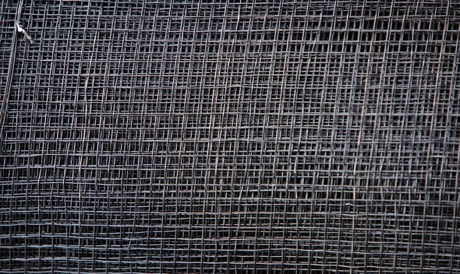
Reinforcing construction mesh: description and application. Welded reinforcement mesh
Welded from construction reinforcement of periodic profile. Technical specifications reinforcement meets the regulatory provisions of GOST 5781-82, is rolled on modern rolling mills of cyclic or continuous operation. Welded reinforcing mesh is used for strengthening brickwork, during the manufacture of various reinforced concrete building structures and special architectural loaded elements.
The strength calculation is carried out taking into account the direction and magnitude of the maximum forces; it can operate in a constantly loaded state. You can buy welded mesh from A3 reinforcement wholesale in rolls or cards; the specific type of packaging depends on the diameter of the reinforcement.
The screed mesh made from A500C reinforcement has an increased coefficient of adhesion to cement-sand mortars, allows you to plaster walls with low strength values, the plaster can withstand significant loads. The metal has no effect of permanent deformation, physical indicators correspond to a specific steel grade. Reinforcing mesh AIII meets the parameters of GOST 23279-85 and is made of hot-rolled carbon structural steel. Can be used during construction or repair of roads with concrete covering, for creating fences, technological and agricultural fences. Welded reinforcing mesh is sold by weight or by total area. Welding is carried out using the spot method, quality control is carried out by the manufacturer. No more than three uncooked knots per square meter of product are allowed.
WELDED REINFORCEMENT MESH
FOR REINFORCED CONCRETE
STRUCTURES AND PRODUCTS
GENERAL TECHNICAL CONDITIONS
GOST 23279-85
STATE COMMITTEE OF THE USSR
ON CONSTRUCTION AFFAIRS
STATE STANDARD OF THE USSR UNION
Resolution State Committee USSR Construction Affairs dated November 28, 1984 No. 194, the introduction date is setfrom 01.01.86
Failure to comply with the standard is punishable by law
This standard applies to welded flat and rolled meshes (hereinafter referred to as meshes), manufactured at construction industry enterprises from reinforcing steel with diameters from 3 to 40 mm inclusive, with rods arranged in two mutually perpendicular directions and intended for reinforcing prefabricated and monolithic reinforced concrete structures and products.
1. CLASSIFICATION
1.1. Meshes are divided: according to the diameters of the rods; according to the location of the working reinforcement. 1.2. Depending on the diameter of the rods, meshes are divided into heavy and light. 1.2.1. Heavy meshes include meshes that have rods with a diameter of 12 mm or more in one direction. 1.2.2. Lightweight ones include meshes with longitudinal and transverse rods with a diameter of 3 to 10 mm inclusive.1.3. Based on the location of the working reinforcement, meshes are subdivided: with working reinforcement in one direction (longitudinal or transverse) and distribution reinforcement in the other direction; with working reinforcement in both directions.2. TYPES, MAIN PARAMETERS AND DIMENSIONS
2.1. Grids are made following types(drawings 1 and 2): 1 - heavy with working fittings in longitudinal direction, the diameter of which is greater than the diameter of the distribution reinforcement; 2 - heavy with working reinforcement in both directions; 3 - heavy with working reinforcement in the transverse direction, the diameter of which is greater than the diameter of the distribution reinforcement; 4 - light with transverse rods across the entire width of the mesh; 5 - light with offset transverse rods.2.2. Meshes are made flat or rolled. Light meshes with longitudinal rods made of reinforcing wire with diameters from 3 to 5 mm inclusive are made in rolls. 2.3. The meshes must have rods of the same diameter in the same direction.2.4. Grids are made with square or rectangular cells.2.5. The diameters of the working reinforcement of the meshes are assigned based on the area required by calculation cross section fittings.2.6. The ratio of the smaller diameter of the rod to the larger one must be at least 0.25.2.7. The main parameters of the grids are given in table 2.8. The distance between the rods - the main pitch of the rods in one direction should be taken the same. 2.8.1. In heavy meshes type 1 for cross bars at the edge of the mesh it is allowed to use an additional step of 100, 200 and 300 mm.2.8.2. In light meshes, in addition to the main step of the rods in the longitudinal direction, it is allowed to use an additional step at the edges of the mesh, as well as at the point of cutting. The additional step of longitudinal rods is taken from 50 mm to the size of the main step, a multiple of 10 mm at the edge of the mesh and a multiple of 50 mm at the cutting point mesh. The additional pitch of the transverse rods is from 50 to 250 mm in multiples of 10 mm. 2.9. The dimensions of the outlets of the longitudinal and transverse rods should be taken equal to 25 mm or multiples of 25 mm in accordance with those indicated in the table. In light meshes made in one strip, the dimensions of the outlets of the longitudinal rods can be taken from 30 to 200 mm, a multiple of 5 mm, and the dimensions of the transverse outlets rods - equal to 15, 20 and 30 mm, as well as from 25 to 100 mm in multiples of 25 mm.Heavy mesh


Lightweight mesh


Grid Options
|
Grid view |
Grid type |
Grid width |
Mesh length |
Rod diameters |
Distance between rods (in axes) - pitch of rods |
Rod release sizes |
||
|
longitudinal |
transverse |
transverse |
longitudinal |
From 650 to 3050 |
From 850 to 9000 |
From 850 to 5950 |
From 850 to 3050 |
From 850 to 6250 |
From 650 to 3800 |
From 850 to 9000 or up to roll length |
From 3950 to 9000 or up to roll length |
2.10. Grids are designated by marks of the following structure
Where x is the designation of the mesh type (clause 2.1); C- letter designation names welded mesh(with the addition of the index “p” for rolled meshes - Ср); d, d 1 - diameter of longitudinal and transverse bars, respectively, indicating the class of reinforcing steel; b, l are the width and length of the mesh, respectively, in centimeters. In the brand of the mesh, the following is additionally given: for light meshes, as well as heavy meshes of type 3 with a main pitch of longitudinal rods of 400 mm after the diameter of the rods (through a dash), the value of the pitch of the rods in millimeters; for meshes with additional pitch - respectively above or below the line, the value of the additional pitch of longitudinal or transverse rods in millimeters (in brackets). For meshes with the dimensions of the outlets of transverse and longitudinal rods differing from 25 mm, the mesh brand is added after indicating the mesh length
Where a 1, a 2 are the values of the releases of the longitudinal rods (for a 1 = a 2, only one value is given in millimeters); a is the value of the releases of the transverse rods in millimeters. Examples of symbols: heavy mesh type 1 with longitudinal bars made of class A-III reinforcing steel with a diameter of 25 mm, with a pitch of 200 mm and with transverse bars made of class A-III reinforcing steel with a diameter of 10 mm, with a pitch of 600 mm, a width of 2050 mm and 6650 mm long, with 25 mm longitudinal and transverse rods:
![]()
flat light mesh type 4 with longitudinal rods made of reinforcing steel class A-IIIC with a diameter of 10 mm and transverse rods made of reinforcing wire class BP-I with a diameter of 5 mm, with a pitch of longitudinal and transverse rods of 100 mm, a width of 2550 mm and a length of 6050 mm, with releases of longitudinal and transverse rods 25 mm:
![]()
rolled mesh type 5 with longitudinal and transverse rods made of reinforcing wire of class BP-I with a diameter of 5 mm, with a main pitch of longitudinal rods of 200 mm and an additional pitch of 100 mm, with a pitch of transverse rods of 150 mm, a width of 2340 mm and a length of 120,000 mm, with outlets longitudinal rods 125 and 175 mm, with releases of transverse rods 20 mm:
3. TECHNICAL REQUIREMENTS
3.1. Meshes should be manufactured in accordance with the requirements of this standard according to working drawings and technological documentation approved in the prescribed manner. 3.2. As working reinforcement in heavy meshes, hot-rolled reinforcing steel rods of class A-III with diameters of 12-40 mm and thermomechanically strengthened reinforcing steel of class At-IIIC with diameters of 12-18 mm should be used. During feasibility studies, the use of hot-rolled rods as working reinforcement is allowed reinforcing steel classes A-II and A-I with diameters of 12-32 mm.3.3. As distribution reinforcement in heavy meshes of type 1, reinforcing steel of class A-III and At-IIIC with diameters of 6-16 is used, in meshes of type 3 - reinforcing steel of class A-II with diameters of 10-16 mm and class A-I with diameters of 6-16 mm.3.4. Light mesh should be made from reinforcing wire of class BP-I with diameters of 3-5 mm, hot-rolled rod reinforcing steel of classes A-III and A-I with diameters of 6-10 mm. It is allowed to use reinforcing wire of class B-I with diameters of 3-10 mm as distribution reinforcement. 5 mm.3.5. The grades of reinforcing steel must correspond to the grades established project documentation(according to requirements building codes and rules for the design of concrete and reinforced concrete structures depending on the operating conditions of the structures) and specified in the order for the production of meshes. 3.6. Reinforcing steel must meet the requirements: rod hot-rolled reinforcing steel of classes A-III, A-II and A-I - GOST 5781-82; rod thermomechanical strengthened reinforcing steel of class At-IIIC - GOST 10884-81; reinforcing wire of classes BP-I and B-I - GOST 6727-80.3.7. Cross-shaped connections of rods in meshes should be made using contact spot welding in accordance with the requirements of GOST 14098-85. Welding modes must comply with the requirements of SN 393-78.3.8. In meshes with working reinforcement made of smooth rod reinforcing steel of class A-I, all intersections of the rods must be welded. In meshes with working reinforcement of a periodic profile (rod and wire), it is allowed to weld the intersections of rods through one or two intersections in a checkerboard pattern, if in working There are no special instructions in the drawings. In the reinforcing mesh, no more than two unwelded intersections of rods are allowed in an area of 1 m 2 of the mesh from among the intersections subject to welding. 3.9. Rods at welding points during tensile testing (weakened at intersections and joints) must have a breaking force or temporary tensile strength not lower than that required by GOST 10922-75.3.10. Requirements for the shear strength of welded joints of rods are in accordance with GOST 10922-75. If welded joints bars made of reinforcing steel of a periodic profile, located in two or one direction, do not have equal strength requirements, then the rejection load during shear testing must be at least 50% of the tensile strength of the reinforcing wire or the temporary tensile strength of reinforcing steel of a smaller diameter. 3.11. Cross-shaped connections of the mesh rods should not be destroyed by impact when the meshes are freely dropped from a height of 1 m.3.12. Butt connections of reinforcing steel bars should be made using contact butt welding according to GOST 14098-85. Welding modes - according to SN 393-78. Working reinforcement on a rod length of 6 m should not have more than two butt joints, and on a rod length of 12 m - more than three butt joints. Butt joints of rods of the same direction within a step reinforcement in the other direction is allowed through at least three bars.3.13. The values of the relative settlement in cross-shaped joints of rods (in fractions of the smaller diameter of the welded rods) should be for reinforcing steel classes: A - I from ........................... ........................... from 0.16 to 0.5 A - III, A t-IIIC and A - II. ........................... from 0.2 to 0.8 Bp - I and B - I ...... ......................................... from 0.2 to 0.53.14. The values of actual deviations of the geometric parameters of the meshes should not exceed the limits specified in GOST 10922-75.3.15. Longitudinal and transverse rods in meshes must be straight. The values of actual deviations from the straightness of the rods should not exceed 6 mm over a rod length of 1 m.4. ACCEPTANCE RULES
4.1. Acceptance of meshes should be carried out in batches in accordance with the requirements of GOST 10922-75 and this standard.4.2. In each mesh or roll selected from the batch, the following are additionally checked: the dimensions of the outlets; the straightness of the rods; the amount of draft of the rods. 4.3. If unsatisfactory test results are obtained for at least one of the indicators, a repeat test is carried out on a double sample. The results of the re-inspection apply to the entire batch. If, during re-inspection, at least one mesh does not meet the requirements of GOST 10922-75 and this standard, all meshes are subject to piece-by-piece acceptance.5. CONTROL METHODS
5.1. Methods for monitoring and testing meshes must comply with those established by GOST 10922-75 and this standard. 5.2. The width and length of flat mesh, the pitch of longitudinal and transverse rods, the dimensions of the outlets, the straightness of the rod and the difference in the length of the diagonals, as well as the width of the rolled mesh, the pitch of its longitudinal and transverse rods, the dimensions of the outlets and the straightness of the transverse rods are checked with a tape measure according to GOST 7502-80 or metal ruler according to GOST 427-75.5.3. Cross-shaped connections are checked for impact at the mesh production and packaging stations by freely dropping the meshes from a height of 1 m onto concrete base or on metal pads.6. MARKING, TRANSPORTATION AND STORAGE
6.1. Flat meshes must be tied into bags. The weight of the package should not exceed 3 tons.6.2. A package of mesh must be tied with soft wire in at least four places, and a roll of mesh - in at least three places.6.3. At least two metal or plywood tags must be attached to each bag and roll of nets, indicating: the name or trademark of the manufacturer; symbol nets according to clause 2.10; number of nets in the bag; weight of the bag or roll in tons; batch number and date of manufacture. Tags must be attached to different sides of the bag and roll. 6.4. Each batch of mesh supplied by specialized factories of reinforcing products must be accompanied by a quality document, which indicates: the name and address of the manufacturer; number and date of issue of the document; batch number; name of the products indicating their brands and quantity in the batch; date of manufacture. The document must be signed by the employee responsible for technical control of the manufacturer.6.5. Nets should be transported in a horizontal position. When loading, transporting and unloading nets, measures must be taken to ensure their safety from damage. Methods for performing loading and unloading operations must comply with the stipulated safety rules in construction.6.6. Nets should be stored indoors. Packages of mesh should be stored separately by brand in stacks no more than 2 m high. Rolls of mesh should be stored in no more than three tiers. When storing nets between stacks, a free passage with a width of at least 0.5 m must be provided.6.7. During storage and transportation, each package must be supported by wooden pads and pads with a thickness of at least 30 mm. Linings under the nets should be laid on a dense, carefully leveled base. When storing nets in stacks, the spacers between the bags along the height of the stack should be located vertically, one above the other.Use in construction is fixed nearby traditional technologies. Without it, it is impossible to build multi-story monolithic buildings or create durable reinforced concrete structures. However, the reinforcing mesh also includes different types rolled metal We will tell you about their features in detail.
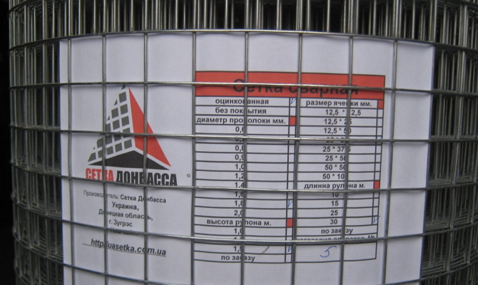
Technical parameters of welded reinforcement mesh
Rolled metal is divided into light and heavy; its assignment to one category or another is based on the raw materials used. Thus, for the production of light rolled metal, VR-1 steel wire is used, in accordance with GOST 6727-80. Its diameter is 4-5 mm. For mid-category products, the same type of wire is used, but with a diameter of 6-8 mm. Heavy welded reinforcing mesh is made from wire with a diameter of 10-12 mm, as well as reinforcing bars of categories A500C, B500C with a three-sided periodic profile. They are laid in the longitudinal and transverse directions and spot welded.
Production of products in cards ensures the convenience of their use in construction. Standard x  The length of the cards is 2000-6000 mm, width - 1000-2400 mm. The advantage of using reinforcing mesh in construction is to reduce the cost of materials without compromising the quality of the work performed. Productivity increases - the intensity of work increases 12 times. Modern metal rolling enterprises offer products not only with standard, but also with custom sizes. This makes it possible to build according to individual projects.
Possibility of using reinforcement mesh
Thanks to its robust, reliable and simple design this type Rolled metal is popular not only in the construction industry. Along with it, it is used to install fences for summer cottages, construction sites. Moreover, the rigidity of this design when using wire of medium and large diameter is higher. Along with the TsPVS mesh, it is used for reinforcing concrete and cement screed, arrangement of self-leveling floors. It is used to make durable frames for structures, including greenhouses, greenhouses, and animal enclosures. Depending on specific tasks, it is always possible to choose reinforced metal products for their implementation.
Welded reinforcement mesh (WAM) is used in a number of important construction activities. It is indispensable for reinforcing reinforcement of monolithic reinforced concrete structures and for other work.
1 Reinforcing mesh – and where it is used!
SAS represents steel mesh, made by cold drawing from low-carbon wire. Its cells are connected to each other by welding. Profile finished product can be periodic or ordinary smooth.
A variety of protective coatings can be applied to the surface of the mesh. They, firstly, increase the technical performance of the mesh structure, and secondly, significantly expand the scope of its application.
Reinforcing mesh made of steel, also called reinforced, is very reliable and durable. It is most often used in the following areas:
- Construction. SAS is used in the construction and arrangement of walls, guaranteeing them unique strength properties. If you take a mesh with rods of increased thickness, you can use it to create foundations in structures and buildings of different orientations and complexity. Reinforced mesh products are also suitable for performing other restoration and repair activities in the field of modern construction.
- Men at work. The use of steel reinforcement mesh guarantees road surfaces highest quality. Their installation becomes faster and easier, and the strength of the resulting structure is very high level. It is also considered advisable to use mesh for reinforcement when carrying out planned road repairs.
- Household. Low carbon wire structures can now be seen on many home gardens and garden plots. In this case, reinforced SAS makes it possible to build any frame structures, be it large greenhouses or small greenhouses, as well as all kinds of fencing.
- Finishing work. The described mesh wire products have proven themselves in interior decoration premises. Light types of SAS provide high-quality alignment unevenness on wall and ceiling surfaces and at the same time optimize and speed up plastering activities.
In addition, reinforcing mesh is currently very actively used by bridge builders. It is used to strengthen bridges, their supports and other elements of such structures.
2 Advantages of grids - competitors, envy!
SAS has a truly unique combination of excellent performance characteristics and technical indicators (weight, strength, etc.). Due to this, it can be used in the most complex industrial and construction sites, always getting an impeccable result of work.
Reinforced mesh is described by the following advantages of use:
- Multifunctionality - there is no such industry in modern industrial production, wherever SAS is used. And every day the areas of its application are expanding.
- Reasonable cost of material made from wire with a low carbon content - competing meshes are inferior to SAS in terms of the cost of their production. Increasing costs for the production of steel products naturally increases their selling price.
- Cost-effectiveness of work – reduction of time for construction and other activities, as well as simplification of the technological process.
- Small specific gravity, ease of fastening, safety of operation and ease of installation

Also worth noting big choice geometric dimensions reinforced mesh allowed by GOST 23279–2012. We will consider this State Standard, which describes all the requirements for SAS, in more detail below. In addition, finished mesh products are transported without any problems and can be stored in almost any conditions.
All of these advantages are achieved due to the fact that SAS is manufactured using innovative equipment according to the latest technologies, which are accepted throughout the civilized world. In the production of wire mesh with a small amount of carbon used, it can also be used. Due to this, the finished mesh structures become highly resistant to mechanical external influences and obtain an excellent strength indicator.

To increase the anti-corrosion protection of SAS, a special layer (most often zinc) can be applied to its surface. Such processing is carried out using electrolytic technology or by hot application. protective coating. Both methods have proven themselves well. Typically, the technology is chosen that makes it possible to obtain a layer of a given thickness and a certain appearance in each specific case.
3 GOST 23279 – what kind of mesh should be used for reinforcement?
This standard describes rolled and flat SAS with a cross section of 3–40 mm, in which the rods, which are elements of the mesh structure, are located perpendicular to each other. The products under consideration according to GOST 23279 are divided into different types according to the method of placement of reinforcement (working) and the cross-section of the rods.
Reinforcement in welded mesh made of low-carbon wire can be located in the transverse and longitudinal directions, only in the transverse or only in the longitudinal. Based on the cross-section of the rod, products are divided into light and heavy. By the latter, GOST means SAS, in which the rods in one direction have a cross-section of more than 12 mm. Lightweight structures are those with transverse and longitudinal rods no more than 10 mm in diameter.

There are five types of welded steel mesh:
- With longitudinal reinforcement (working), the cross-section of which is larger than the cross-section of the distribution reinforcement. Such products are classified as heavy.
- Reinforcement in both directions, heavy.
- With transverse reinforcement large section, heavy.
- With offset rods located transversely, lightweight.
- With rods (transverse) for the entire available width of the SAS.
GOST allows the production of wire structures with rectangular and square cells, in rolls or flat view. Please note that only 3–5 mm lightweight SAS can be produced in rolls, the weight of which does not exceed the values specified in the standard.
The cross-sections of the working reinforcement of reinforcement products are determined taking into account the cross-sectional area (transverse) of the reinforcing elements (a calculation should be performed that takes into account not only the diameter, but also the weight of the latter). The ratio of the cross-section of the smaller rod to the larger one must be 0.25. SAS must (required!) have rods of the same diameter in one direction.
The weight of the mesh is determined by its type (light, heavy), length, width and cross-section of the rods used. If the structure is made, for example, from rods with a diameter of 4 mm, with dimensions of 200 by 600 cm and with cells of 20 by 20 cm, the mass of one square meter will be equal to 0.99 kg. But the weight of meshes with the same parameters, but made from rods with a cross-section of 8 mm, will already be 3.95 kg.
4 Other requirements of Gosstandart - this is important!
According to GOST 23279, for heavy meshes for reinforcement, the working reinforcement is reinforcing steel (bar) with a section of 10-40 mm of classes A600C, A500C, A400. It is allowed to use rods of hot-rolled alloys A240. Light SAS are made from wire with a cross-section of up to 5 mm ( type B-I, Вр-I) or from reinforcing steel 6–10 mm of classes A240, A500C, A400, B500C.
GOST clearly stipulates that the intersections of rods in wire and rod periodic reinforcement can be welded in a checkerboard pattern through two or one position. In this case, at all intersections the last two rods in the mesh structure should be connected. If SAS is made from A240 steel, all intersections without exception are welded.
Cross-shaped joints in the described products are welded using spot technology in accordance with GOST 14098. Welding modes for performing this operation are selected based on the requirements of the regulatory documentation existing at the enterprise.

The tensile strength and breaking force of the mesh rods at the places where they are welded are checked according to standard 10922. The shear strength must comply with the provisions of the same GOST.
Acceptance of SAS is carried out in rolls or in batches. In addition to all standard analyses, products undergo additional checks for the draft of the rods and the value of their straightness.

Reinforced mesh is tied into bags weighing no more than three tons. It is mandatory that the packages are tied in four areas using soft metal wire. If the product is supplied in rolls, the bundle is performed in three or more places.
The nets are transported in a horizontal position. In this case, it is necessary that the bags rest on 3-centimeter spacers or similar thicknesses wooden blocks. SAS is stored in the same way.
GOST 23279-2012
INTERSTATE STANDARD
WELDED REINFORCEMENT MESH FOR REINFORCED CONCRETE STRUCTURES AND PRODUCTS
Are common technical specifications
Welded reinforcing meshes for reinforced concrete structures and products. General specifications
MKS 91.190
Date of introduction 2013-07-01
Preface
The goals, basic principles and basic procedure for carrying out work on interstate standardization are established by GOST 1.0-92 "Interstate standardization system. Basic provisions" and GOST 1.2-2009 "Interstate standardization system. Interstate standards, rules, recommendations for interstate standardization. Rules for development, adoption, application, renewal and cancellation."
Standard information
1 DEVELOPED by the Russian Academy of Engineering
2 INTRODUCED by the Technical Committee for Standardization TC 465 "Construction"
3 ADOPTED by the Interstate Scientific and Technical Commission for Standardization, Technical Regulation and Conformity Assessment in Construction (Appendix B to the Protocol dated June 4, 2012 N 40)
The following voted for the adoption of the standard:
Short name of the country according to MK (ISO 3166) 004-97 | Abbreviated name of the national authority government controlled construction |
|
Azerbaijan | State Committee for Urban Planning and Architecture |
|
Ministry of Urban Development |
||
Kyrgyzstan | Gosstroy |
|
Ministry of Construction and Regional Development |
||
Ministry of Regional Development |
||
Tajikistan | Agency for Construction and Architecture under the Government |
|
Uzbekistan | Gosarchitectstroy |
4 By Order of the Federal Agency for Technical Regulation and Metrology dated November 29, 2012 N 1306-st, the interstate standard GOST 23279-2012 was put into effect as a national standard Russian Federation from July 1, 2013
5 INSTEAD GOST 23279-85
Information about changes to this standard is published in the annual information index " National standards", and the text of changes and amendments - in the monthly information index "National Standards". In case of revision (replacement) or cancellation of this standard, the corresponding notification will be published in the monthly information index "National Standards". The relevant information, notification and texts are also posted in information system common use- on the official website of the Federal Agency for Technical Regulation and Metrology on the Internet
1 area of use
1 area of use
This standard applies to welded flat and rolled meshes (hereinafter referred to as meshes), manufactured at construction industry enterprises from reinforcing steel with diameters from 3 to 40 mm inclusive, with rods located in two mutually perpendicular directions, and intended for reinforcing prefabricated and monolithic reinforced concrete structures and products.
2 Normative references
This standard uses normative references to the following standards:
GOST 427-75 Metal measuring rulers. Specifications
GOST 5781-82 Hot-rolled steel for reinforcement of reinforced concrete structures. Specifications
GOST 6727-80 Cold-drawn low-carbon steel wire for reinforcement of reinforced concrete structures. Specifications
GOST 7502-98 Metal measuring tapes. Specifications
GOST 10922-90 * Welded reinforcement and embedded products, welded connections of reinforcement and embedded products of reinforced concrete structures. General technical conditions
________________
* The document is not valid on the territory of the Russian Federation. GOST 10922-2012 is valid, hereinafter in the text. - Database manufacturer's note.
GOST 14098-91 Welded connections of reinforcement and embedded products of reinforced concrete structures. Types, designs and sizes
Note - When using this standard, it is advisable to check the validity of the reference standards in the public information system - on the official website of the Federal Agency for Technical Regulation and Metrology on the Internet or using the annual information index "National Standards", which was published as of January 1 of the current year, and according to the relevant issues of the monthly information index "National Standards" for the current year. If the reference standard is replaced (changed), then when using this standard you should be guided by the replacing (changed) standard. If the reference standard is canceled without replacement, then the provision in which a reference is made to it is applied in the part that does not affect this reference.
3 Classification
3.1 Grids are divided into:
- by rod diameters;
- according to the location of the working fittings.
3.2 Depending on the diameter of the rods, meshes are divided into heavy and light.
3.2.1 Heavy meshes include meshes that have rods with a diameter of 12 mm or more in one direction.
3.2.2 Lightweight includes meshes with longitudinal and transverse rods with a diameter of 3 to 10 mm inclusive.
3.3 Based on the location of the working reinforcement, the meshes are divided into:
- with working fittings in one of the directions (longitudinal or transverse) and distribution fittings in the other direction;
- with working fittings in both directions.
4 Types, main parameters and dimensions
4.1 Meshes are made of the following types (see Figures 1 and 2):
- type 1 - heavy with working fittings in the longitudinal direction, the diameter of which is greater than the diameter of the distribution fittings;
- type 2 - heavy with working fittings in both directions;
- type 3 - heavy with working fittings in the transverse direction, the diameter of which is greater than the diameter of the distribution fittings;
- type 4 - lightweight with transverse rods across the entire width of the mesh;
- type 5 - lightweight with offset transverse rods.
Figure 1 - Heavy mesh
Type 2
Type 3
Figure 1 - Heavy mesh
Figure 2 - Lightweight meshes
Type 5
Figure 2 - Lightweight meshes
4.2 Meshes are made flat or rolled.
Light meshes with longitudinal bars made of reinforcing steel with diameters from 3 to 5 mm inclusive are produced in rolls.
4.3 Nets must have rods of the same diameter in the same direction.
4.4 Grids are made with square or rectangular cells.
4.5 The diameters of the working reinforcement of the meshes are assigned based on the condition of the cross-sectional area of the reinforcement required by calculation.
4.6 The ratio of the smaller diameter of the rod to the larger one must be at least 0.25.
4.7 The main parameters of the grids are given in Table 1.
Table 1 - Grid parameters
In millimeters
Grid view | Grid type | Grid width | Mesh length | Rod diameters | Distance between rods (in axes) - pitch of rods | Rod outlet sizes |
||
longitudinal | transverse | transverse | longitudinal and |
|||||
From 650 to 3050 | From 850 to 9000 | Multiples of 25 |
||||||
From 850 to 5950 | Multiples of 25 |
|||||||
From 850 to 3050 | From 850 to 6250 | |||||||
From 650 to 3800 | From 850 to 9000 or up to roll length | 100 (150) | 100 (75) | |||||
From 3950 to 9000 or up to roll length | ||||||||
* It is allowed to use rod spacing of 100 and 300 mm in the grids of standard design documentation for reinforced concrete structures. Notes 1 Heavy meshes of type 1 with a width of 1500 to 3050 mm with longitudinal rods with diameters of 36 and 40 mm and type 3 with a length of 3050 to 6250 mm are produced using single-point machines and suspended welding tongs before the development of automated equipment production. 2 By agreement with the manufacturer, the use of heavy mesh type 1 and light flat mesh with a length of up to 11500 mm is allowed. 3 In lightweight mesh type 5, the length of the transverse rods is from 0.85 to 0.90 of the mesh width. 4 The distances between the longitudinal and transverse rods of light mesh, indicated in brackets, may be accepted during a feasibility study. |
||||||||
________________
Probably an error in the original. Should read: See 4.9 (letter of Rosstandart TK 465 “Construction” dated December 27, 2016 N TK-736/2016). - Database manufacturer's note.
4.8 The distance between the rods - the main step of the rods in one direction - should be taken the same.
4.8.1 In heavy meshes of type 1, for transverse rods at the edge of the mesh, an additional step of 100 is allowed; 200 and 300 mm.
4.8.2 In light meshes, in addition to the main step of the rods in the longitudinal direction, it is allowed to use an additional step at the edges of the mesh, as well as at the point of cutting it.
The additional pitch of the longitudinal rods is taken from 50 mm to the size of the main step, a multiple of 10 mm at the edge of the mesh and a multiple of 50 mm at the point where the mesh is cut.
The additional pitch of the transverse rods is taken from 50 to 250 mm, a multiple of 10 mm.
4.9 The dimensions of the outlets of longitudinal and transverse rods should be taken equal to or multiples of 25 mm in accordance with those indicated in Table 1.
In light meshes made in one strip, the dimensions of the outlets of the longitudinal rods can be taken from 25 to 200 mm, multiples of 5 mm, and the dimensions of the outlets of the transverse rods - equal to 15; 20 and 30 mm, as well as from 25 to 100 mm, multiples of 25 mm.
4.10 Grids are designated by marks of the following structure
where is the designation of the mesh type (see 2.1);
- designation of the name of the welded mesh (with the addition of an index for rolled meshes);
, - diameters of longitudinal and transverse bars, respectively, indicating the class of reinforcing steel;
, - width and length of the grid, cm, respectively.
In the designation of the mesh brand, the following is additionally given:
- for light meshes, as well as heavy meshes of type 3 with a main pitch of longitudinal rods of 400 mm after the diameter of the rods (through a dash) - the value of the pitch of the rods in millimeters;
- for meshes with additional spacing - above the line or below the line, respectively, the value of the additional spacing of longitudinal or transverse bars in millimeters (in parentheses).
For meshes with outlet sizes of transverse and longitudinal rods different from 25 mm, the designation of the mesh brand after the designation of the mesh length is supplemented with the following designation:
where , are the values of the releases of the longitudinal rods (only one value is given), mm;
- the value of the releases of the transverse rods, mm.
Examples of symbols:
- heavy mesh type 1 with longitudinal bars made of reinforcing steel class A500C with a diameter of 25 mm, with a pitch of 200 mm and with transverse bars made of reinforcing steel class A500C with a diameter of 10 mm, with a pitch of 600 mm, width 2050 mm and length 6650 mm, with longitudinal outlets and cross bars 25 mm:
Flat light mesh type 4 with longitudinal bars made of reinforcing steel class A500C with a diameter of 10 mm and transverse bars made of reinforcing steel B500C with a diameter of 5 mm, with a pitch of longitudinal and transverse bars of 100 mm, a width of 2550 mm and a length of 6050 mm, with releases of longitudinal and transverse bars 25 mm:
Rolled mesh type 5 with longitudinal and transverse bars made of reinforcing steel class B500C with a diameter of 5 mm, with a main pitch of longitudinal bars of 200 mm and an additional pitch of 100 mm, with a pitch of transverse bars of 150 mm, a width of 2340 mm and a length of 120,000 mm, with releases of longitudinal bars 125 and 175 mm, with 20 mm crossbar outlets:
5 Technical requirements
5.1 Meshes should be manufactured in accordance with the requirements of this standard according to working drawings and technological documentation approved in the prescribed manner.
5.2 As working reinforcement in heavy meshes, reinforcing steel bars of classes A500C, A600C and A400 (A-III) with a diameter of 10-40 mm should be used.
During feasibility studies, the use of hot-rolled reinforcing steel bars of class A240 (A-l), with a diameter of 10-32 mm, as working reinforcement is allowed.
5.3 As distribution reinforcement in heavy meshes of type 1, reinforcing steel of classes A400 (A-III), A500C, B500C and A600C with diameters of 6-16 mm is used, in meshes of type 3 - reinforcing steel of classes A400 (A-III), A500C, B500C and A600C with a diameter of 10-16 mm and A240 (A-l) with a diameter of 6-16 mm.
5.4 Lightweight mesh should be made from reinforcing steel of class B500C with a diameter of 4-5 mm, reinforcing wire of class Bp-I with a diameter of 3-5 mm and rod reinforcing steel of classes A400 (A-III), A500C, B500C and A240(A-I) with a diameter of 6- 10 mm.
As distribution fittings, it is allowed to use reinforcing steel of class B500C with a diameter of 4-5 mm and reinforcing wire class B-l with a diameter of 3-5 mm.
5.5 The grades of reinforcing steel for the production of meshes must correspond to the grades established by the design documentation (in accordance with the requirements of building codes and regulations for the design of concrete and reinforced concrete structures, depending on the operating conditions of the structures), specified in the order for the production of meshes.
5.6 Reinforcing steel must meet the requirements:
- rod reinforcing steel classes A400 (A-III) and A240 (A-I) - GOST 5781;
- rod reinforcing steel of classes A500C and B500C - active regulatory documents*;
_______________
* In the Russian Federation, GOST R 52544 applies to reinforcing steel of classes A500C and B500C.
- rod reinforcing steel class A600C - current regulatory documents;
- reinforcing wire of classes Bp-I and B-l - GOST 6727.
5.7 Cross-shaped connections of rods in meshes should be carried out by resistance spot welding in accordance with GOST 14098.
Welding modes must comply with the requirements of current regulatory documents.
5.8 In meshes with working reinforcement made of smooth bar reinforcing steel of class A240 (A-l), all intersections of the rods must be welded.
In meshes with working reinforcement of a periodic profile (rod and wire), it is allowed to weld the intersections of the rods through one or two intersections in a checkerboard pattern, if there are no special instructions in the working drawings. The two outermost bars in the meshes must be welded at all intersections
In the reinforcing mesh, no more than two unwelded intersections of rods are allowed in an area of 1 m of the mesh from among the intersections subject to welding.
5.9 The breaking force or temporary tensile strength of rods at welding points during a tensile test (weakened at intersections and joints) must not be lower than required by GOST 10922.
5.10 Requirements for the shear strength of welded joints of rods - in accordance with GOST 10922.
If welded joints of bars made of reinforcing steel of periodic profile, located in two or one direction, are not subject to equal strength requirements according to GOST 10922, then the rejection load during shear testing should be at least 30% of the tensile strength of the reinforcing wire or the lesser tensile strength of the reinforcing steel diameter
5.11 Cross-shaped connections of the net rods should not be destroyed by impact when the nets are freely dropped from a height of 1 m.
5.12 Butt joints of reinforcing steel bars should be made by contact butt welding in accordance with GOST 14098.
Welding modes - according to current regulatory documents.
Working reinforcement on a rod length of 6 m should not have more than two, and on a rod length of 12 m - more than three butt joints.
Butt connections of rods in one direction within the reinforcement pitch in another direction are allowed through at least three rods.
5.13 The values of relative settlement in cross-shaped joints of rods (in fractions of the smaller diameter of the welded rods) should be for reinforcing steel classes A240 (A-l), A400 (A-III), B500C, A500C and A600C from 0.2 to 0.5.
5.14 The values of actual deviations of the geometric parameters of the grids should not exceed the limits specified in GOST 10922.
5.15 Longitudinal and transverse rods in meshes must be straight.
The values of actual deviations from the straightness of the rods should not exceed 6 mm over a rod length of 1 m.
6 Acceptance rules
6.1 Grids are accepted in batches in accordance with the requirements of GOST 10922 and this standard.
6.2 In each mesh or roll selected from the batch, the following is additionally checked:
- sizes of releases;
- straightness of the rods;
- the amount of settlement of the rods.
6.3 If unsatisfactory test results are obtained for at least one of the indicators, a re-check is carried out on a double sample. The results of the re-inspection are applied to the entire batch.
If, during re-checking, at least one mesh does not meet the requirements of GOST 10922 and this standard, all meshes are subject to piecemeal acceptance.
7 Control methods
7.1 Methods for monitoring and testing meshes must comply with those established by GOST 10922 and this standard.
7.2 The width and length of flat mesh, the pitch of longitudinal and transverse rods, the dimensions of the outlets, the straightness of the rod and the difference in the length of the diagonals, as well as the width of the rolled mesh, the pitch of its longitudinal and transverse rods, the dimensions of the outlets and the straightness of the transverse rods are checked with a tape measure in accordance with GOST 7502 or a metal one ruler according to GOST 427.
7.3 Cross-shaped connections for impact are checked at the mesh production and packaging stations by freely dropping the meshes from a height of 1 m onto a concrete base or metal pads.
8 Labeling, transportation and storage
8.1 Flat meshes must be bundled. The weight of the package should not exceed 3 tons.
8.2 A package of mesh must be tied with soft wire in at least four places, and a roll of mesh in at least three places.
8.3 At least two metal or plywood tags must be attached to each bag and roll of nets, indicating:
- name or trademark of the manufacturer;
- symbol of grids according to 4.10;
- number of meshes in the package;
- mass of the package or roll, t;
- batch number and date of manufacture.
Tags must be attached to different sides of the bag and roll.
8.4 Each batch of mesh supplied by specialized enterprises of reinforcing products must be accompanied by a quality document, which indicates:
- name and address of the manufacturer;
- number and date of issue of the document;
- batch number;
- name of the products, indicating their brands and number in the batch;
- date of manufacture.
The document must be signed by the employee responsible for technical control manufacturer.
8.5 Nets should be transported horizontally.
When loading, transporting and unloading nets, measures must be taken to ensure their safety from damage. Methods for performing loading and unloading operations must comply with safety regulations provided for in construction.
8.6 Nets must be stored indoors. Packages of mesh should be stored separately by brand in stacks no more than 2 m high. Rolls of mesh should be stored in no more than three tiers. When storing nets between stacks, a free passage of at least 0.5 m in width must be provided.
8.7 During storage and transportation, each package must be supported by wooden pads and pads with a thickness of at least 30 mm.
Linings under the nets should be laid on a dense, carefully leveled base. When storing nets in stacks, the spacers between the bags along the height of the stack should be located vertically, one above the other.
Electronic document text
prepared by Kodeks JSC and verified against:
official publication
M.: Standartinform, 2013


