Guidelines for the design of concrete and reinforced concrete structures made of heavy concrete without pre-tensioning
Guidelines for the design of concrete and reinforced concrete structures made of heavy concrete (without prestressing)(3331 kb.)
Available files (1):
| 1.doc | 3331kb. | 30.11.2011 00:05 |
- See also:
- [document]
- A manual for the design of concrete and reinforced concrete structures made of heavy concrete without prestressing reinforcement (to SP 52-101-2003) [document]
- Bazhenov Yu.M., Alimov L.A., Voronin V.V., Magdeev U.Kh. Technology of concrete, building products and structures [document]
- NPAOP 26.6-1.02-00 Labor protection rules for workers of concrete and reinforced concrete plants [document]
- Bazhenov Yu.M. Concrete technology [document]
- Guidelines for the repair of concrete and reinforced concrete structures of transport structures, taking into account the compatibility of materials [standard]
- Guidelines for the design of reinforced concrete structures with rigid reinforcement [standard]
- Guidelines for strengthening reinforced concrete structures with composite materials [standard]
- Berezovsky B.I., Evdokimov N.I., Zhadanovsky B.V. etc. Construction of monolithic structures of buildings and structures [document]
- Design Guide for Precast Concrete Columns for Single-Story Industrial Buildings [standard]
- Design Guide for Reinforced Concrete Structures with Beamless Floors [standard]
- Reinforced concrete structures of BNTU [lecture]
1.doc
BEAMS
3.91.A beam (rib, purlin) is a linear, usually bending element, used in the structures of buildings and structures separately or as part of floors, retaining walls, foundations and other structures. Beams can rest freely or restrained on two or more supports. In this regard, according to the number of spans and the nature of support, beams are distinguished:A) single-span, freely lying;
Aspects of a sustainable construction federation
The construction complex is planned as solid construction with facade to brick clinker with core high density. The windows and glass elements are heavily clogged. Sustainability is the guiding principle for the future. In the construction industry, the topic is becoming increasingly important in the face of climate change, rising energy prices and scarce resources. This is why the Federal Government has made the Sustainable Building Directive mandatory. Sustainable construction is the construction of buildings in such a way that they are equally sustainable, economically, environmentally, socially and urbanistically.
B) single-span, fixed on one or both supports;
B) multi-span continuous;
D) console.
According to the manufacturing method, reinforced concrete beams can be prefabricated or monolithic.
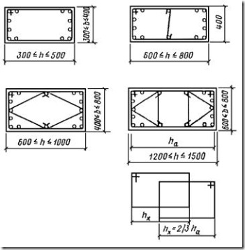
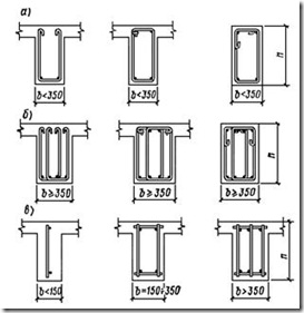
By form cross section beams, as a rule, can be rectangular, T-beam (with a flange on top or bottom) and I-beam. It is recommended that monolithic beams be constructed with a rectangular cross-section, and prefabricated beams with a T-section or I-beam. Examples of prefabricated beam designs are shown in Fig.83 .
Public buildings here are role models and must meet a range of requirements: functional equity, safety and cost-effectiveness, architectural quality and design, energy efficiency and the use of innovative building materials, methods and procedures.
Soundproofing and acoustic concept
To meet the required soundproofing requirements, it was planned to house the "additional loud" applications and utilize the high occupancy in two separate structures, each with their own foundations and complete structural separation. Rooms requiring protection must also be equipped with a sound-absorbing wall or ceiling cladding or equivalent sound-absorbing surfaces. In addition, a report was prepared on room acoustics for sports ground for space rail shooting and digital radio control center.
Rice. 83. Examples of precast concrete beam designs
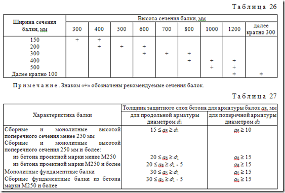
The dimensions of the cross sections of beams are assigned in accordance with paragraph.3.1 of this Guide. Recommended sizes rectangular sections take according to the table26 .
3.92. Minimum thickness The protective layer of concrete for the reinforcement of beams under normal operating conditions (no aggressive influences) must meet the requirements of paragraphs.3.3 ; 3.4 ; 3.5 And 3.6 and taken according to the table.27 of this Guide.
Room acoustics requirements for sports area footage taken from the Planning Guide for Space Blinds. Ceiling and wall coverings are made from sound-absorbing material approved for gliding systems. To avoid flutter echoes in longitudinal direction, the wall is directed into the control room with an 8° inclination. The digital radio center is partially equipped with an acoustic ceiling.
Planning data New service building Stralsund-Ddholm
In addition, the walls are made on the side of the room with sound-absorbing wall coverings. Damage to steel reinforcement 1 Damage caused by carbonation 2 Damage caused by chloride 3 Possible weak points in concrete 4 Technical and physical basis Modernity Comparison various methods construction 1 Protection of contaminated surfaces groundwater floors 2 General technical and economic justification.
The ends of the longitudinal working reinforcement bars that are not welded to the anchoring parts must be spaced from the end of the beam at a distance of at least:
10 mm - for prefabricated beams up to 9 m long inclusive;
15 mm - for monolithic beams up to 6 m long inclusive with a diameter of reinforcement bars up to 40 mm inclusive;
20 mm - for monolithic beams with a length of more than 6 m with a diameter of reinforcement bars up to 40 mm inclusive.
The chloride it contains can cause significant corrosion damage to steel reinforcement in concrete, which is sometimes not visible and can only be detected by specialists. Have not been used in construction or renovation for many years optimal solutions for protection against chloride corrosion, and the situation is rarely satisfactory even from the point of view of ease of maintenance. Currently, synthetic polymer coatings are mainly used to prevent chloride corrosion. These solutions are still largely unknown in the construction industry and are practically unused because the economics are sometimes uncertain, the state of the art is controversial and details regarding usability are often unclear.
Table 26
| Beam section width, mm | Beam section height, mm |
||||||||
| 300 | 400 | 500 | 600 | 700 | 800 | 1000 | 1200 | further multiples of 300 |
|
| 150 | |||||||||
| 200 | |||||||||
| 300 | |||||||||
| 400 | |||||||||
| 500 | |||||||||
| Further multiples of 100 | |||||||||
Note . The “ ” sign indicates recommended beam sections.
Table 27
The core of the research results on this topic is a master's thesis, which examines various approaches to solutions in technical, legal and economic aspects. The main findings are that despite higher investment, bitumen construction may be more cost-effective in the long run because the costs life cycle are reduced due to lower maintenance and repair needs. These bitumen structures are well established in standards and are in accordance with the state of the art.
And the fact that through the porous surface of the bitumen there is often stronger buffering and evaporation of the injected water, which can sometimes be omitted drainage systems and gradients. It becomes obvious that an individual corrosion protection concept must be developed for each garage. To do this, all construction methods must be tested on a specific frame.
| Beam characteristics | Thickness of the protective layer of concrete for beam reinforcementA b, mm |
|
| for longitudinal reinforcement with diameterd 1 | for transverse reinforcement with diameterd 2 |
|
| Prefabricated and monolithic with a cross-sectional height of less than 250 mm | £15 A b ³ d 1 | A b ³ 10 |
| Prefabricated and monolithic with a cross-sectional height of 250 mm or more: | ||
| from concrete of design grade less than M250 | £20 A b ³ d 1 | A b ³ 1 5 |
| from concrete of design grade M250 or more | £20 A b ³ d 1 - 5 | A b ³ 1 5 |
| Monolithic foundation beams | £3 0 A b ³ d 1 | A b ³ 1 5 |
| Prefabricated Foundation Beams from concrete grade M250 and more | £3 0 A b ³ d 1 - 5 | A b ³ 1 5 |
3.93.Beams are reinforced with longitudinal and transverse reinforcement, and in case of knitted frames, also bent.
The cross-sectional area of the working reinforcement of the beams is determined by calculation and must satisfy the requirements of paragraph.3.8 of this Guide.
3.94.For longitudinal working knitted reinforcement of beams with a section height of 400 mm or more, it is recommended to use rods with a diameter of at least 12 mm. For longitudinal reinforcement installed for structural reasons, as well as for longitudinal mounting rods of welded frames of prefabricated beams, it is allowed to use rods of smaller diameters.
Initial situation. Garages and underground garages are currently the subject of intense debate among experts. The focus is on the professional, legally compliant and economical protection of steel reinforcement against chloride corrosion by construction industry professionals. In this context, usability plays a role important role and therefore questions about drainage or until the end of the last century, reinforced concrete components of garages and underground garages were usually not sealed or coated, so they were not protected from chloride corrosion.
It is recommended to appoint longitudinal working reinforcement from rods of the same diameter. If rods are used different diameters(the number of which is recommended is no more than two), rods of larger diameter should be placed in the first row, in the corners of the section and, for knitted frames, in the places where the clamps are bent.
The longitudinal working reinforcement bars should be placed evenly across the cross-sectional width of the beam or rib and, as a rule, in no more than three rows. In this case, the third row must have at least two rods. Placing the rods of subsequent rows above the gaps (in the span) or under the gaps (on supports) of the previous rows is prohibited.
These surface protection systems based on epoxy resins, relatively soft, elastic and cross-shaped. However, they offer little resistance to mechanical stress. Vehicle. The result is high cost, so the overall economic situation, including efforts to maintenance, is often not satisfactory. These resin-based surface protection systems are also relatively hard, durable and have high resistance to mechanical loads.
They are listed in the leaflet Parking garages and underground garages of the German Association for Concrete and construction technologies 2 and are described as extended service options. This method of construction is controversial and does not appear to be fully developed, especially in legal terms. Therefore, this construction will be questioned as to whether it can be considered a recognized rule of technology. An alternative to synthetic polymer coatings are bitumen structures. They are still largely unknown in terms of technical diversity, general economic accounting and their normative classification.

Rice. 84. Location of longitudinal reinforcement in the cross section of the beam
A- welded fittings;b- knitted reinforcement
3.95.Clear distances between individual rods of longitudinal knitted reinforcement, as well as between longitudinal rods of adjacent welded mesh must be accepted at least largest diameter rods and no less for lower reinforcement 25 mm, and for upper reinforcement - 30 mm.
This is often assumed without defining physical boundary conditions such as the flatness of the surface or the buffering of the coating in question and professional assessment. Matthias Gottschalk Practical possibilities to protect the surface of multi-storey car parks and underground garages from the effects of chloride 4 demonstrate significant changes in the above aspects, and also evaluate various solutions from an economic point of view and clarify incompletely developed subtopics.
The work was supervised by Professor Silvia Stürmer, University of Konstanz for Technology, Science and Design, Faculty of Civil Engineering and Diploma-Ing. Damage to steel reinforcement Reinforced concrete load-bearing components are generally designed to withstand design loads while maintaining regulatory safety levels. The prerequisite for this is that the concrete and reinforcement are not damaged. Over time, it loses its main protective effect, causing corrosion of the reinforcing steel. This is accompanied by an increase in the volume of corrosion products.
The maximum number of longitudinal rods of the same diameter that can be arranged in one row along the width of the cross section of the beam is given in Table.28 .
When the lower reinforcement is located in more than two rows along the height of the section, the distances between the rods located in the third and subsequent rows must be at least 50 mm. The location of welded and knitted reinforcement in the section of beams is shown in Fig.84 .
The concrete breaks or rust forms so that the damage is also clearly visible to lay people and therefore controlled. Since the damage process is usually relatively slow and countermeasures are manageable, this topic will not be discussed here. Figure 1: Spraying concrete covering and exposed fittings in the base area of the underground car park 2 Damage caused by chloride. In case of damage caused by chloride, the situation is different, which is mainly introduced by cracks and penetrates into the steel reinforcement.
Here, for example, reinforcing steel can be literally destroyed by corrosion. This means that in the event of chloride-induced corrosion on the surface concrete slab There should be no crushed stone or traces of rust that can be recognized by non-professionals. If steel reinforcement is inserted for a static or sealing reason, the stability and moisture protection of the entire reinforced concrete structure is compromised. On the other hand, if the gain concrete component inserted only for structural reasons or against shrinkage stress at an early stage, damage and corrosion process due to pitting can be considered pointless.
Table 28
| Beam section width, mm | Reinforcement in the beam section | The maximum number of longitudinal rods of the same diameter placed in one row of a beam with a diameter of the rods, mm |
||||||||||
| 12 | 14 | 16 | 18 | 20 | 22 | 25 | 28 | 32 | 36 | 40 |
||
| 150 | Upper | 3 | 3 | 3 | 2 | 2 | 2 | 2 | 2 | - | - | - |
| Lower | 3 | 3 | 3 | 3 | 3 | 2 | 2 | 2 | - | - | - |
|
| 200 | Upper | 4 | 4 | 4 | 4 | 3 | 3 | 3 | 3 | 2 | - | - |
| Lower | 5 | 4 | 4 | 4 | 4 | 3 | 3 | 3 | 2 | - | - |
|
| 300 | Upper | - | - | 6 | 6 | 5 | 5 | 5 | 4 | 4 | 3 | 3 |
| Lower | - | - | 7 | 6 | 6 | 5 | 5 | 5 | 4 | 3 | 3 |
|
| 400 | Upper | - | - | - | - | 7 | 7 | 6 | 6 | 6 | 5 | 4 |
| Lower | - | - | - | - | 8 | 8 | 7 | 6 | 6 | 5 | 4 |
|
| 500 | Upper | - | - | - | - | 9 | 9 | 8 | 8 | 7 | 6 | 6 |
| Lower | - | - | - | - | 10 | 10 | 9 | 8 | 7 | 6 | 6 |
|
3.96.In the ribs of prefabricated panels, decking, often ribbed floors and so on. with a width of 150 mm or less, as well as in individual beams with a section width of 150 mm or less, provided that these ribs and beams are designed for a uniformly distributed load (not exceeding 400 kgf/m 2 ) and are not designed for torsion, it is allowed to install one longitudinal working rod in the span and bring it to the support, or install one “ladder” type mesh. In beams with a width of more than 150 mm, the number of longitudinal working rods installed in the span and brought to the support must be at least two.
In beams with knitted reinforcement and four-shear stirrups should be installed in the span and brought to the support of at least four rods. Schemes for reinforcing cross sections of beams with welded and knitted frames are shown in Fig.85 .
Compared to the component's normal service life of typically 50 years, it cannot penetrate in such quantities that it causes significant damage to the reinforcement. This is only possible through weak points in the system through which chloride can attack the reinforcing steel. These are primarily cracks, construction joints, defects in concrete such as gravel nests and microstructural defects, as well as structurally incorrectly planned or executed construction expansion joints. Errors in registration, compaction and subsequent treatment of concrete, as well as imperfections in joints, can be avoided, but cracks are not completely avoided.

Rice. 85. Reinforcement schemes for beam sections
A- knitted reinforcement, double-cut clamps;b- the same, with four-cut clamps;V- welded fittings
The lower reinforcement, which is brought to the outermost free supports of the beams, should be placed beyond the edge of the support to the length of the anchorage in accordance with paragraph.2.42 of this Guide.
As a rule, they arise, in particular, from shrinkage processes. It is recommended to use a seal to safely operate garages and underground garages, despite constant cracking. Because it must be removed carefully depending on the concentration if chloride is included in the component.
This refers to the three-dimensional reduction in volume as reinforced concrete dries. 7, concrete technologies and operational efforts. It should be noted that chloride also penetrates into small cracks that are considered impermeable to water in terms of transporting water in liquid form. Therefore, it is important when and to what extent cracks develop and whether they increase over time. In particular, this question should be answered regarding the cracking properties of coatings and seals. To adapt seals to these boundary conditions.
3.97.In order to save reinforcing steel in beams reinforced with welded frames, it is recommended to break off part of the span reinforcement bars above them, which should be brought to the support, in the span, without bringing them to the supports. The locations of rod breaks are determined by calculation.
In beams reinforced with knitted frames, the span reinforcement rods, if their number is more than two with double-shear stirrups and more than four with four-shear stirrups, do not break, but can bend onto the supports.
Little known in this context is physical property relaxation in mineral building materials. Relaxation refers to a special form of creep and describes the process of time-dependent stress relief in a reinforced concrete component with a constant, unchanging part geometry. Thus, in the young component, stresses and cracks are at their maximum, and later new cracks or existing cracks no longer increase. This maximum is in the usual construction sizes within three to four years after production of the component.
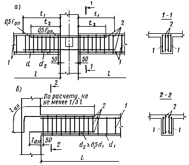
3.98.Reinforcement of secondary beams with welded frames is recommended according to Fig.86 , and knitted - according to Fig.87 .

Rice. 86. Reinforcement of secondary monolithic beams with welded mesh
A- extreme supports; b- middle support; V- detail for installing a butt rod with working reinforcement made of round smooth rods;G- the same, from periodic profile rods;1 - secondary beam;2 - main beam; 3 - span reinforcement of the secondary beam;4 - support mesh of the secondary beam;5 - butt rod diameterd With ; 6 - span reinforcement of the main beam;t 1 - according to calculation, but not less 1 / 3 l; t 2 - according to calculation, but not less 1 / 4 l

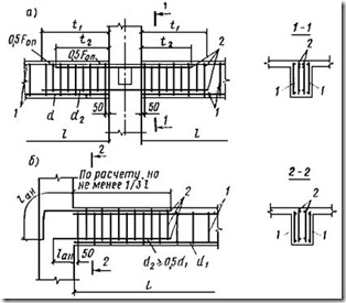
Rice. 87. Reinforcement of secondary monolithic beams with separate rods
A- extreme supports; b- middle support; t 1 - according to calculation, but not less 1 / 3 l; t 2 - according to calculation, but not less 1 / 4 l
The length of the span welded frames of secondary beams is assigned equal to size span in the clear, and special joint rods are inserted beyond the edge of the supports. Joint rods must be provided on intermediate supports of secondary beams, and also on the extreme supports of these beams, if the extreme support is the main beam or purlin connected to the secondary beam monolithically. These rods are installed at the level of the span working reinforcement rods of the beams and their number must correspond to the number of span meshes. The diameter of the joint rods must be at least 10 mm and at least half the diameter of the working mesh rod. The total cross-sectional area of these rods must, in addition, be no less than the minimum percentage of reinforcement for the cross-section of the beam on the support.
Butt rods, if they are of a periodic profile, are inserted beyond the edge of the support into a span of at least 15, and if the rods are smooth, then by 15dneed to add one step cross bars secondary beams and plus 50 mm.
If compressed reinforcement is needed on a support, the cross-section of the butt rods is determined by calculation and they are inserted beyond the edge of the support into the span for the length of the lap joint for compressed rods in accordance with paragraph.2.46 of this Guide.
Rods of the lower knitted reinforcement of monolithic beams (Fig.87 ) in cases where in the support sections the lower reinforcement is not required according to the calculation, it is recommended to extend beyond the edge of the intermediate support by at least the lengthl en for tensile rods in compressed concrete (see paragraph.2.40 of this Guide).
If the lower reinforcement on the intermediate support is taken into account in the calculation as compressed or tensile, then the joint of adjacent barsyears is carried out in accordance with the instructions for making overlapped reinforcement joints without welding (clause2.46 of this Manual), while joints of all rods brought to the support can be made in one section.
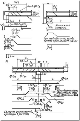
3.99.On the extreme supports of the secondary beams, monolithically connected to reinforced concrete purlins, it is necessary to provide upper reinforcement with a cross-sectional area of at least 1 / 4 cross-sectional area of the reinforcement in the adjacent span (Fig.86 , A and 87, A). The bars of this reinforcement should be inserted into the span at 1 / 6 clear span of the beam and seal it on the support in accordance with the requirements of paragraph.2.40 of this Guide.
3.100.On the outermost supports of the beam, embedded in the wall (brick, etc.), to absorb a possible pinching moment, upper reinforcement must be provided, which can be assigned in the form of special rods, but, as a rule, the existing mounting reinforcement is sufficient here. When reinforcing with individual rods, the mounting reinforcement should therefore always be placed beyond the edge of the support by a lengthl en in accordance with paragraph.2.40 (rice. 87 , A), and in welded mesh when making mounting fittings from smooth rods, the conditions of paragraph.2.42 (rice. 86 , A) of this Manual.
3.101.On intermediate (middle) supports of multi-span continuous secondary monolithic beams, the upper reinforcement is specified by calculation. The break points of the rods of this reinforcement should, as a rule, also be determined by calculation, and in one section it is allowed to break no more than three rods with double-shear clamps and no more than four with four-shear clamps. When a beam is subjected to a temporary, uniformly distributed load that does not exceed triple the constant load, half (in area) of the upper rods can be inserted beyond the edge of the support into the adjacent span by 1 / 3 span in the light, and half - on 1/4 (Fig. 86 , b and 87, b). In multi-spanbeams with different spans that differ from each other by no more than 20%, the breakage points of the rods in all spans are assigned the same (along the larger span), and if the difference in spans is more than 20%, the rods are inserted into the smaller span to a length determined along the adjacent span (more). If a small span is located between two large ones, at least two support rods should be pulled from adjacent spans across the entire small span on top, even if they are not required by calculation.
3.102. Negative points on intermediate supports of multi-span continuous beams, it is sometimes necessary to reinforce the ribs with lower compressed reinforcement. If such reinforcement is necessary (according to calculations), it is recommended to design this section of the beam as follows:
a) when reinforcing with welded mesh, butt rods are installed in accordance with paragraph.3.98 this Guide;
B) when reinforced with separate rods:
If required section compressed reinforcement does not exceed the cross-section of the rods brought to the support from each span separately, then these rods are joined on the support with an overlap without welding, and the joint is carried out in one section, and the length of the overlap is taken in accordance with clause.2.46 this Guide;
if the cross-section of the span reinforcement brought to the support is not enough, then it should be overlapped and short pieces should be added, the cross-sectional area of which is determined by calculation. Shortyare launched in each span on 1 / 6 lfrom the axis of the support or on 1 / 8 lfrom the edge of the support (a larger value is taken).
3.103.Reinforcement of main beam supports monolithic floors Welded reinforcement is recommended to be made with special vertical meshes of the type shown in Fig.88 .
The scheme for reinforcing the main beams with individual rods is similar to the scheme for reinforcing the secondary beams shown in Fig.87 .
Rice. 88. Reinforcement of supports of monolithic main beams with welded ones grids
A- middle support; b- extreme support; 1 - span grid;2 - support mesh; t 1 - according to calculation, but not less 1 / 3 l; t 2 - according to calculation, but not less 1 / 4 l
3.104.At the side surfaces of beams with a cross-sectional height of more than 700 mm, structural longitudinal rods must be installed with distances between them in height of no more than 400 mm and a cross-sectional area of at least 0.1% of the cross-sectional area of concrete with dimensions equal to: along the height of the element - the distance between these rods , along the width of the element - half the width of the element rib, but not more than 200 mm (Fig.89 ). These rods must be connected with studs with a diameter of 6 - 8 mm from class reinforcement A - I in increments of 500 mm along the length of the beam.
3.105.Vertical transverse reinforcement in beams and ribs with a height of more than 150 mm must always be installed. It is permissible not to install transverse reinforcement in beams and ribs with a height of 150 mm or less.
Transverse reinforcement may not be placed at the edges of thin ribs and beams with a width of 150 mm or less, the width of which is only one longitudinal rod or welded mesh. In this case, the calculation requirements set out in paragraph.3.36 chapters of SNiP II -21-75.
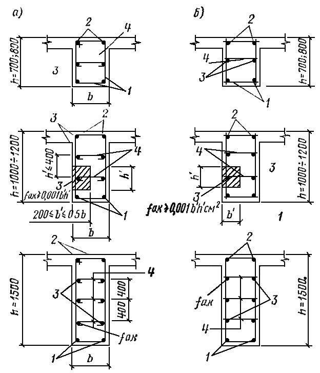
Rice. 89. Placement of structural longitudinal rods at the side faces in the cross section of the beam
A - with knitted reinforcement;b - with welded fittings;1 - longitudinal working reinforcement;2 - longitudinal mounting reinforcement;3 - longitudinal structural rod with cross-sectional areaf a.c ³ 0.001 b¢ h¢ ; 4 - studs or cross rods,d= 6 - 8 mm
3.106.The diameter of the transverse rods in welded mesh and beam frames is taken by calculation. In this case, it is necessary to take into account the welding conditions according to table.4 .
The diameter of the clamps in the knitted beam frames is taken by calculation and must be at least: 6 mm ath£ 800 mm; 8 mm at h> 800 mm.
In this case, both in welded and knitted frames, the diameter of the longitudinal rods must be no less than the diameter of the transverse ones.
3.107.Distances between vertical transverse rods or stirrups in beams that do not have bent reinforcement, in cases where transverse reinforcement is required by calculation or for design reasons specified in paragraph.3.105 of this Manual, must be no less than those required by calculation and accepted (see Fig.90 ):
a) on supporting areas (equal under uniform load 1 / 4 span, and with concentrated loads - the distance from the support to the nearest load, but not less 1/4 span):
at section heighth£ 450 mm - no more h/ 2 and no more than 150 mm;
at section heighth> 450 mm - no more h/ 3 and no more than 500 mm;
b) on the rest of the span at the section heighth> 300 mm - no more than 3/4 h and no more than 500 mm.
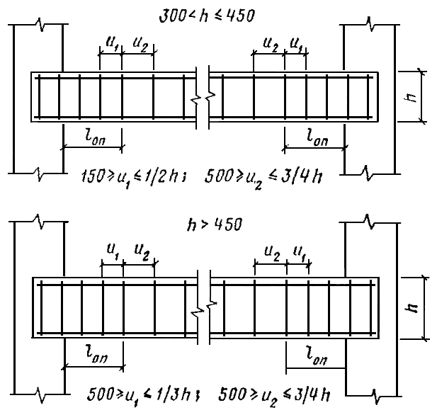
Rice. 90. Location of transverse reinforcement in beams without bends
3.108.The distances between transverse rods (clamps) in beams with compressed longitudinal reinforcement taken into account in the calculation should be taken according to table.25 of this Guide.
3.109.In knitted frames of middle beams of monolithic ribbed floors, including multi-span continuous floors, monolithically connected at the top by a slab along the entire length with temporary loads on the floor of 3 tf/m 2 and it is less recommended to install open clamps. Closed clamps are installed in separate (not monolithically connected to the slab) beams of rectangular or T-section, in the outer beams of monolithic ribbed floors, in beams with calculated compressed reinforcement, as well as in the middle beams of monolithic ribbed floors designed for a live load of more than 3 tf/m 2 .
3.110.In beams with knitted reinforcement designed for torsion, closed clamps should be installed with their ends overlapping by 30d, and for welded frames, vertical and horizontal transverse rods must be welded in accordance with paragraph.2.34 and this Guide.
3.111.Connections of longitudinal and transverse rods in welded mesh beams must provide anchorage for transverse reinforcement, for which welded joints must be of equal strength.
In knitted frames, the clamps must be designed in such a way that longitudinal rods must be located in the bridges of their bend, as well as the bend of the end hooks (in the absence of bypass of the ends).
It is recommended that each clamp cover no more than five tension rods and no more than three compression rods in one row. With a larger number of rods in one row, as well as with a beam width of 350 mm or more, it is recommended to switch to four-shear or multi-shear clamps.
The clamp designs used for beams with knitted reinforcement are shown in Fig.1 And 85 . In this case, the width of the four-shear clamp, depending on the number of rods in one row of the beam and the number of rods between the internal branches of the clamps, is determined according to table.29 .
Table 29
| Beam width b, mm | Meaning b X , mm, four-shear clamps with the number of longitudinal rods in one row of the beam |
|||||
| 5 | 6 | 7 | 8 | 9 | 10 |
|
| When the number of longitudinal rods between the internal branches of the clamps |
||||||
| 3 | 2 | 3 | 4 | 3 | 4 |
|
| 350 | 230 | 190 | 205 | 220 | - | - |
| 400 | 270 | 225 | 240 | 255 | 225 | 240 |
| 450 | - | 250 | 270 | 295 | 255 | 270 |
| 500 | - | - | 310 | 330 | 290 | 280 |
3.112.At monolithic structures In the thickness of the supports at the intersection of a beam with a column or with a purlin, transverse reinforcement of the beam should not be installed. In such structures, the first clamp or transverse rod should be placed in the span at a distance of 50 mm from the edge of the support.
When supporting monolithic beams on brickwork on the outer support, the first clamp or transverse rod is placed at the end of the beam with the necessary protective layer, and within the middle supports, the installation of clamps continues with the step taken for the span of the beam.
In prefabricated beams, the placement of transverse reinforcement should begin from the end of the element, taking into account protective layers concrete.
3.113.Bent rods should be used in beams reinforced with knitted frames if the calculation requires transverse reinforcement. It is not recommended to use bent rods in welded frames.
The length of the support section of the beam on which the bends are placed is determined by calculation.
The radius of the arc along which the inclined section of the rod is bent must be at least 10d.
The angle of inclination of the bend to the longitudinal axis of the beam, as a rule, should be taken equal to 45°. In beams with a section height of more than 800 mm and in beam-walls, the angle of inclination of the bends can be increased to 60°, and in low beams and in beams designed for concentrated loads, it can be reduced to 30 ° .
3.114.It is preferable to form inclined reinforcement by bending the lower span reinforcement onto supports, which in continuous beams is then transferred through the support to the adjacent span (see Fig.87 ).
If there is a need to increase the number of inclined rods on an intermediate support beyond the number that can be obtained by bending rods from adjacent spans, then short rods with two inclined sections should be installed above this support (rodd k in fig. 87 ) and with two horizontal sections at the bottom to provide anchorage.
The use of short bars with one inclined section and so-called floating bars not connected with the general reinforcement, as well as bars with complex configuration having more than two inclined sections are not allowed.
3.115.In beams with a section width of 200 mm or less, it is allowed to bend one rod in each plane. In beams with a section width of 300 - 400 mm, at least two rods should be bent in the first plane from the support, and in subsequent planes it is allowed to bend one rod at a time. In beams with a section width of more than 400 mm, bending less than two rods in each plane is not allowed.
If the diameters of the bending rods are different, then bends of larger diameters should be located closer to the support.
It is recommended to place the bends of the rods symmetrically relative to the vertical axis of the beam section. If one rod is bent in a section, it should be placed along the axis of symmetry of the section or as close as possible to it. It is not recommended to bend the rods located directly at the side surfaces of the beam; they should be placed at a distance of at least 2 dfrom the side faces of the beam (Fig.91 ).
3.116.The distances between the inclined sections of the rods along the length of the beam are determined by calculation. If the calculation does not give instructions on the location of the planes of the bends, then the distances between them are taken according to Fig.87 .
3.117.The rods of the first bend plane from the support are not taken into account in the calculation as part of the above-support longitudinal reinforcement. The section from which the upper straight section of the bent rod of each plane is fully included in the work for the supporting bending moment is considered to be the section at a distance³
 from the top point of the inclined section of this rod towards the support. Similarly, the lower straight section of the bent rod is completely excluded from the work on the span bending moment in the section at a distance³
from the bottom point of the inclined section towards the span (hereh 0
- the calculated height of the beam section, approximately equal to 0.9 - 0.95 of the height of the beam section).
from the top point of the inclined section of this rod towards the support. Similarly, the lower straight section of the bent rod is completely excluded from the work on the span bending moment in the section at a distance³
from the bottom point of the inclined section towards the span (hereh 0
- the calculated height of the beam section, approximately equal to 0.9 - 0.95 of the height of the beam section).
3.118.Rods bent out of the span in the first and second planes from the intermediate support must be inserted into the adjacent prologue, and those bent in the third and subsequent planes are allowed to be torn off if there is no need for them to work on the supporting bending moment or if it is difficult to place them in the supra-support section in the span above (see Fig.87 ).

Rice. 91 . Designing bent rods
3.119.The upper ends of bent rods that do not pass through the support and adjacent span must end in straight sections with a length of at least 0.8l en , adopted in accordance with the instructions of paragraph.2.40 of this Manual, but not less than 20din stretched and 10din a compressed area. Breakage of the bent rod in the stretched area (bottom) should be avoided. In beams more than one meter high, a bent rod made of smooth reinforcement can only end in a compressed area with a hook without a straight section (see Fig.91 ), and periodic profile bars must always have a straight section.
3.120.Vertical projectionsh o tg. i mm, inclined sections of bent rods depending on the height of the beam sectionh b and the size of the protective layer of concreteA b, are calculated using the following formulas:
 ; (20)
; (21)
; (22)
. (23)
Wherein:  - for secondary beams;
  mm - for main beams, which are adjacent to secondary beams with upper reinforcement with a diameter of up to 20 mm;
  mm - for main beams, which are adjacent to secondary beams with upper reinforcement with a diameter of more than 20 mm.
If d 2 > 20 mm, or d 1 > 20 mm, or ( d 1 d 2 ) > 40 mm, then in formulas (21 ), (22 ) And ( 23 ) should be substituted accordingly(d 2 , d 1 instead of 20 or d 1 d 2 instead of 40; h o tg. i calculated with an accuracy of 10 mm.
Additional instructions for reinforcing beams in areas where concentrated loads are applied
3.121.In sections of beams where concentrated loads are applied, including in places where monolithic secondary beams rest on the main ones, additional reinforcement should be provided according to Fig.92 . The cross-sectional area of this reinforcement is determined by calculation.
Additional reinforcement, depending on the type of main reinforcement, is designed in the form of welded mesh, bends, hangers or quickened clamps. In this case, the number of welded meshes, bends or hangers must be at least two; there must be at least 4 vertical rods in each welded meshÆ 6; bends or hangers must have a diameter of at least 10 mm; bent rods must have a horizontal straight section in the upper zone with a length of at least 0.8l en , accepted according to paragraph.2.40 of this Manual, and no less 20 d, Moreover, if the bends are made of smooth reinforcement, this section should end with a hook.
3.59. Columns or racks are vertical extended elements of a single-story or multi-story frame of a building or structure, usually subject to compression.
Depending on the purpose and position in a one-story building, the columns are divided into main ones, located in the outer and middle rows, and half-timbered ones, located at the ends and sometimes in the outer rows between the main ones (when the size of the wall enclosure structure is less than the pitch of the main columns).
According to the method of construction, columns are distinguished between prefabricated and monolithic.
The cross-sectional shape of the columns can be square, rectangular, I-beam, round (solid or hollow).
In industrial construction, columns of solid square and rectangular cross-section, as well as two-branch ones (Fig. 70), have become widespread and are used, recommendations for the design of which are outlined below.
Rice. 70. Types of precast columns
A- prismatic columns of solid cross-section for one-story craneless buildings; b- stepped columns of solid section for one-story buildings equipped with overhead cranes; V- the same, two-branch columns; G- columns of solid section length multi-storey building; 1 - console for support truss structures; 2 - console for supporting crane beams; 3 - opening for passage device; 4 - console for supporting crossbars of interfloor ceilings
A square cross-sectional shape is recommended for columns in which the longitudinal force is, as a rule, applied centrally, and a rectangular or two-legged one is recommended when there are bending moments in the section. If necessary, short consoles are installed in the columns to support adjacent structures of trusses, crane and other beams. At the same time, to support load-bearing structures coating, the size of the column head must be at least 300 mm when supported on one side and at least 500 mm when supported on both sides. The last size can be reduced to 400 mm if covering structures are supported with a span of up to 12 m. The size of the head must be no less than the cross-sectional size of the upper part of the column.
The shape of the column can be prismatic or stepped. The latter is used for buildings equipped with overhead cranes. Stepped columns consist of a crane and a crane part. In the overhead part of the column, if necessary, openings for passage can be arranged, which must be at least 400 x 1800 mm in size.
3.60. The dimensions of the column sections must be taken such that their flexibility l 0 /r in any direction, as a rule, did not exceed 200 (for rectangular sections), and for columns that are elements of buildings - .
3.61. The cross-sectional dimensions of prefabricated and monolithic columns are assigned in accordance with paragraphs. 3.1. and 3.2. of this Guide. It is recommended to assign them unified in accordance with Table. 22.
The dimensions of the columns in height from the level of the finished floor are taken to be multiples of 600 mm, and below the level of the finished floor - according to the conditions of connection with the foundation.

It is recommended to design the crane parts of the main columns of one-story buildings with a column height of more than 12 - 14 m as two-branch.
3.62. Concrete for columns is used of a design grade not lower than M200.
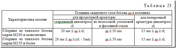
The thickness of the protective layer of concrete for the working reinforcement of columns under normal operating conditions (in the absence of aggressive influences) must meet the requirements of paragraphs. 3.3; 3.4; 3.5; 3.6 of this Manual and accepted according to table. 23.
3.63. The ends of the longitudinal working rods that are not welded to the anchoring parts must be spaced from the end of the element at a distance of at least:
10 mm - for prefabricated columns up to 18 m long inclusive;
15 mm - for prefabricated columns longer than 18 m, as well as supports and masts of any length;
15 mm - for monolithic columns up to 6 m long inclusive with a diameter of reinforcement bars up to 40 mm inclusive;
20 mm - for monolithic columns with a length of more than 6 m with a diameter of reinforcement bars up to 40 mm inclusive.
The ends of the transverse rods of welded column frames must have a protective layer of at least 5 mm.
3.64. The cross-sectional area of the working reinforcement of the column is determined by calculation and must meet the requirements of clause 3.8 of this Manual.
It is not recommended to assign the cross-sectional area of the longitudinal working reinforcement to more than 5% of the cross-sectional area of the column.
It is recommended to reinforce a section of a column that is subject to bending moments of different sign but similar in magnitude with symmetrical longitudinal reinforcement.
3.65. The diameter of the longitudinal working rods of prefabricated columns is recommended to be at least 16 mm. For monolithic columns, as well as for structural reinforcement, it is allowed to use a rod diameter of 12 mm.
3.66. It is recommended to assign all rods of longitudinal working reinforcement to the same diameter. If longitudinal reinforcement is constructed from rods of different diameters, it is allowed to use no more than two different diameters, not counting structural rods. In this case, rods of larger diameter should be placed in the corners of the cross-section of the column.
It is recommended to place longitudinal reinforcement bars on each side of the column cross-section in one row. It is allowed to provide a second row of two rods, placing them near the corners of the cross-section of the column.
It is recommended to place the longitudinal working reinforcement of eccentrically compressed columns along the edges perpendicular to the bending plane of the column. It is recommended to concentrate longitudinal working reinforcement in oblique eccentric compression of columns in the corners of the section.
3.67. The lengths of the longitudinal reinforcement bars of a column should, as a rule, be assigned in such a way that the need for joints is eliminated. If it is necessary to install lap joints (without welding), they should be located primarily in places where the column cross-section changes.
In stepped columns, the longitudinal reinforcement of the upper section must be inserted into the concrete of the lower section by at least the length of the anchorage.
In two-branch columns, breakable rods must be inserted beyond the edge of the spacer separating the panel in which they are required by calculation, to a length determined by the calculation, but not less than the required anchorage length.

Rice. 71 Diagram of the arrangement of joints of longitudinal rods of monolithic columns of multi-story buildings
A- with the same cross-section of the columns of the upper and lower floors; b- with a slight difference in the sections of the columns of the upper and lower floors; V- with a sharp difference in the sections of the columns of the upper and lower floors
In multi-storey monolithic columns, joints should be made at the level of the top of the floors using outlets similar to outlets from foundations (see paragraphs 3.45; 3.46 of this Guide). With a floor height of less than 3.6 m or with longitudinal reinforcement d³ 28 mm joints are recommended to be installed across the floor.
Releases of rods from a column with a large cross-section of the lower floor into a column with a smaller cross-section top floor It is recommended to carry out in accordance with Fig. 71. In this case, the transfer of rods from one floor of the column to another is carried out by bending them with a slope of no more than 1:6 (Fig. 71, A, b). Part of the column rods of the lower floor can be brought to the top of the floor (Fig. 71, b) and do not insert it into the column of the upper floor if it is not needed there according to calculations. In case of a sharp difference in the sections of the columns of the upper and lower floors, outlets should be arranged by installing special rods in the quantity required for the column of the upper floor (Fig. 71, V).
The embedment depth (anchorage length) of the working longitudinal reinforcement in the column of the lower floor must be no less than that required in clause 2.40, and the amount of overlap of the rods at the joint must be in clause 2.46 of this Manual.
3.68. The distance between the axes of the longitudinal reinforcement bars of the columns should be no more than 400 mm.
If the distance between the working rods is more than 400 mm, it is necessary to install structural rods with a diameter of at least 12 mm between them, so that the distances between the longitudinal rods are no more than 400 mm.
The clear distance between longitudinal rods should be no less than 30 mm in prefabricated columns, no less than 50 mm in monolithic columns, and in both cases no less than the diameter of the rod.
3.69. The design of transverse reinforcement must ensure the fastening of compressed rods from their lateral buckling in any direction.
Transverse reinforcement must be installed at all surfaces of the column, near which longitudinal reinforcement is installed.
To form a spatial frame, flat welded meshes located at opposite faces of the column must be connected to each other by transverse rods welded by contact spot welding to the corner longitudinal rods of the mesh, or with pins connecting these rods.
If the meshes of opposite faces of the column have intermediate longitudinal rods, then the latter must be connected to each other using pins at least through one and at least 400 mm across the width of the edge. It is allowed not to install studs if the width of a given column face is 500 mm or less, if the number of longitudinal rods at this face does not exceed four. At large sizes cross-section of the column, in addition to the meshes located at the edges, it is recommended to install intermediate welded meshes.
Examples of reinforcement of column sections with welded mesh are shown in Fig. 72.

Rice. 72. Examples of reinforcement of column sections with the recommended number of rods with welded mesh
1 - welded mesh; 2 - welded mesh or connecting rod; 3 - connecting rod (hairpin); 4 - clamp; 5 - individual longitudinal reinforcement bars; 6 - transverse reinforcement in the form of welded mesh
The design of knitted column clamps should be such that the longitudinal rods (at least through one) are located at the bends of the clamps, and these bends are located at a distance of no more than 400 mm across the width of the column section. If the width of the edge is no more than 400 mm and the number of longitudinal rods at this edge is no more than four, it is allowed to cover all the longitudinal rods with one clamp.
Examples of reinforcement of column sections with knitted reinforcement are shown in Fig. 73.
Rice. 73. Examples of reinforcement of column sections with the recommended number of rods with knitted frames
3.70. The diameters of the transverse reinforcement bars, depending on the design of the reinforcement frame and the diameters of the longitudinal bars, should be taken no less than those indicated in the table. 24. The diameter of the transverse reinforcement is assigned according to the largest diameter of the longitudinal reinforcement in the column section.

Notes: 1. The studs for connecting the welded mesh into the frame are installed with the spacing adopted for the transverse rods of the mesh.
2. When calculating the percentage of reinforcement μ, the total saturation of the column section with longitudinal reinforcement is taken into account.
3. If the section is reinforced with longitudinal bars of different diameters, then the distance between the transverse reinforcement is assigned according to the smaller of them.
4. When assigning distances between transverse reinforcement bars, it is permitted not to take into account longitudinal bars that are not taken into account in the calculation, if the diameter of these bars does not exceed 12 mm and does not exceed half the thickness of the protective layer of concrete.

Rice. 74. Scheme of column reinforcement with transverse reinforcement in the form of a spiral
3.71. The distances between transverse reinforcement at each face of the column should be assigned:
at Rа.с £ 4000 kgf/cm 2 - no more than 500 mm and no more than 20 d with welded frames or 15 d when knitted;
at Rа.с = 4500 kgf/cm 2 and Rа.с = 5000 kgf/cm 2 - no more than 400 mm and no more than 15 d with welded frames or 12 d when knitted, where d- the smallest diameter of compressed longitudinal rods.
In columns with a saturation of longitudinal reinforcement of more than 3%, transverse reinforcement should be installed in increments of no more than 10 d and no more than 300 mm. In this case, the clamps must be welded to the longitudinal rods.
In joints of longitudinal working reinforcement with an overlap without welding, regardless of whether the column is reinforced with welded or knitted frames, it is recommended to use clamps. The distances between clamps in the joint area should be no more than 10 d.
Here d- diameter of compressed longitudinal rods of working reinforcement (smaller).
3.72. When designing columns with transverse reinforcement in the form of a spiral, taken into account in the calculation as indirect reinforcement (calculation by section core), the following conditions must be met (Fig. 74):
a) the spirals must be round in plan;
b) the distances between the turns of the spiral in the axes must be at least 40 mm, no more than 1/5 of the cross-sectional diameter of the column core covered by the spiral, and no more than 100 mm;
c) spirals must cover all working longitudinal reinforcement;
d) spiral winding diameter D n must be at least 200 mm.
If it is necessary to create a passage at floor level, the distance from the finished floor to the bottom of the first overhead strut must be at least 1.8 m.
At the lower end of a two-branch column, it is recommended to install the spacer below the floor level. When assigning a connection to this spacer, it is necessary to take into account the conditions for unifying forms, transportation and installation of columns. It is recommended to combine the lower edges of the spacer and branches.
a) private - (1 - 2) h V;
b) upper (at the point of transition from two branches to one) - no less than double the height of the section of the row strut;
c) lower (located within the foundation glass) - at least 200 mm.
The cross-sectional width of the struts should be taken equal to the width of the branch.

Rice. 75 Design of the interface between an intermediate strut and a branch of a two-branch column
a- reinforcement with welded frames; b- the same, knitted reinforcement; 1 - spacer reinforcement; 2 - branch reinforcement; 3 - additional welded mesh; 4 - additional clamps; 5 - additional cross rods (studs)
3.74. The longitudinal reinforcement of the struts, if both branches of the column are compressed, is assumed to be symmetrical. If, according to calculations, one of the branches is stretched, the reinforcement is assumed to be asymmetrical. The longitudinal rods of the struts must be anchored in the concrete of the branches in accordance with paragraphs. 2.40 or 2.41 of this Guide. It is allowed to perform anchoring according to Fig. 26.
3.75. At the junction points between the row strut and the branches (Fig. 75), additional reinforcement should be installed in the form of welded mesh or clamps in combination with short vertical rods. The meshes are installed in the planes of the transverse vertical reinforcement of the spacer frame.
The transverse bars of the branch frames within the spacer must be preserved. If they interfere with the installation of the spacer reinforcement, they should be cut out and then replaced with studs.
3.76. The upper strut is reinforced (Fig. 76) with working longitudinal reinforcement located along the upper and lower edges of the strut, as well as bends, horizontal and vertical transverse reinforcement (rods or clamps).
The pitch of horizontal transverse rods or clamps in the upper strut should be no more than 150 mm and no more than 1/4 of its height, and the pitch of vertical rods or clamps should be no more than 200 mm. The total area of horizontal clamps must be at least 0.001 bh 0 , where h 0 is the working height of the strut section, and b- cross-section width of the strut. The bends in the spacer should intersect the lower half of the inclined line AB, coming from the angle of junction of the supracolumn to inner corner branch junctions. The cross-section of the bends crossing the lower half of the line must be at least 0.002 bh 0 . Bends may not be provided if they are not needed according to calculations.
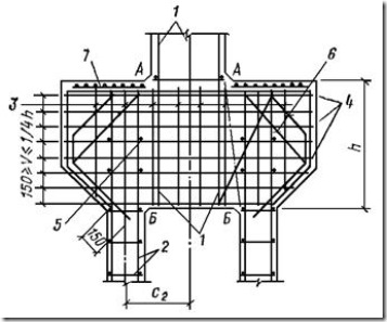
Rice. 76. Design of the interface of the upper strut with the branch of the crane two-branch column of the middle row
1 - fittings of the overhead crane branch; 2 - fittings of the crane branch; 3 - vertical reinforcement of the spacer (step no more than 200 mm); 4 - horizontal strut reinforcement; 5 - spacer bends; 6 - bends of the crane console; 7 - meshes of indirect reinforcement
3.77. When constructing an opening in the overhead part of the column, it should be bordered at the top and bottom with horizontal rods, the cross-sectional area of which is determined by calculation. The diameter of these rods must be at least 16 mm.
Column consoles
3.78. Consoles in columns are arranged in order to create the necessary platform for supporting various elements adjacent to the column on different levels structures (trusses, crane beams, crossbars, purlins, etc.).
Consoles can be single-sided or double-sided. The latter should be arranged in one plane, especially in prefabricated columns. If the consoles on the column need to be located in perpendicular planes or if the console is needed to support elements transmitting a small local load (from working platforms, stairs, etc.), then such consoles are recommended to be designed in the form of steel tables, providing the corresponding embedded parts for their fastening.
With an overhang of 100 - 150 mm, the console may not have a haunch and be designed rectangular (Fig. 77, A). With an overhang of more than 150 mm, the console must have a haunch with an angle of inclination a, which is usually taken to be 45° (Fig. 77, b).
The width of the console should be equal to the width of the column. An exception may be consoles installed in wide columns to support foundation beams. The height of the console and its reinforcement are determined by calculation. The consoles are reinforced with transverse and longitudinal reinforcement.

Rice. 77. Short column consoles
A- rectangular console; b- console with wut
3.79. The transverse reinforcement of short consoles with welded and knitted column frames is designed as follows (Fig. 78):
at h £ 2,5A- in the form of inclined clamps along the entire height of the console (Fig. 78, A);
at h > 2,5A- in the form of bent rods and horizontal clamps along the entire height of the console (Fig. 78, b);
at h > 3,5A And Q £ R p bh 0 - in the form of horizontal clamps without bent rods, which in this case may not be provided; Here h 0 is taken in the support section of the consoles.
In all cases, the pitch of the clamps should be no more h/4 and no more than 150 mm; the diameter of the bent rods should be no more than 1/15 of the length of the bend l otg and no more than 25 mm. In this case, the total cross-sectional area of inclined clamps (see Fig. 78, A) and bent rods (see Fig. 78, b), crossing the upper half of a line of length l, connecting the points of application of force Q and the connection between the lower edge of the console and the edge of the column must be at least 0.002 bh 0 .
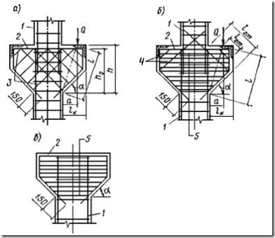
Rice. 78. Reinforcement scheme for short consoles
A- inclined clamps; b- bent rods and horizontal clamps; V- horizontal clamps; 1 - column frame; 2 - longitudinal working reinforcement of the console; 3 - inclined clamps; 4 - bends; 5 - horizontal clamps
3.80. It is recommended to direct the bends in short consoles from the lower corner of the consoles to the opposite upper corner. With a large overhang or a high console height, it is allowed to make bends at an angle of 30 or 60°, respectively, or place the bends in two planes, placing each plane at an angle of 45°.
At large number straight and bent rods, the upper and lower sections of bent rods can be placed in the second row.
3.81. The ends of the longitudinal reinforcement of the tensile zone of the one-sided console, located within the height of the column, must be brought beyond the edge of the column by the amount l an, adopted according to clause 2.40 of this Guide, and in any case must be brought to the opposite edge of the column (Fig. 79).
At the free end of the console, it is also necessary to provide anchorage for longitudinal reinforcement in cases where the distance l 3 from the load application center Q to the edge of a straight rod less: 15 d- for concrete of design grade below M300; 10 d- for concrete of design grade M300 and higher.
Anchoring here is performed by welding washers or corners to this reinforcement according to Fig. 79, V, G. The design of the anchors must meet the requirements of clause 2.41, b of this Guide. Installation of anchors is not necessary in the consoles on which prefabricated beams rest along the extension of the console, if the joints of these beams are reliably monolithic and the upper reinforcement in the beams is provided as in a frame with rigid units, and the lower reinforcement of the beams is welded through embedded parts to the reinforcement of the consoles.

Rice. 79. Anchoring of longitudinal working reinforcement of short consoles
A, b- without additional anchoring at the free end of the console; V, G- with additional anchoring at the free end of the console; 1 2 - steel plate; 3 - T-welding; 4 - arc welding; 5 - steel corner

Rice. 80. Rectangular short console with rigid reinforcement
3.82. Diamond-shaped clamps and studs do not provide transverse reinforcement for the column within the console.
3.83. If the height of the console is limited, it is permissible to use rigid reinforcement according to Fig. 80.
3.84. If necessary, according to calculations, indirect reinforcement meshes should be provided under the supporting embedded parts of the crane console, which should be designed in accordance with clause 3.53 of this Manual.
Features of the design of columns of prefabricated reinforced concrete frames
3.85. Columns of prefabricated frames should be designed in lengths that ensure ease of manufacture, transportation and installation. If it is necessary to construct tall columns in the absence of appropriate lifting and transport equipment, it is permissible to construct them from two elements with an assembly joint.
In such joints between the ends of the joined columns, a centering gasket should be provided in the form of a steel plate anchored in concrete or welded during installation to the distribution sheet of the embedded part (Fig. 81). The dimensions of the centering spacer are taken to be no more than 1/3 of the corresponding size of the column section.
The shape and size of the undercuts are determined by the number of joined rods. The total height of undercuts is taken to be no less than 300 mm and no less than 10 d, Where d-larger diameter of outlets.

Rice. 81. Rigid joint of prefabricated columns with bath welding of reinforcement outlets
A- with four corner reinforcement outlets; b- with reinforcement outlets located along the perimeter of the section; 1 - reinforcement outlets; 2 - embedment concrete in undercuts; 3 - centering gasket; 4 - meshes of indirect reinforcement; 5 - bathroom welding
Saturation coefficient with indirect reinforcement (see paragraph 2.41, A) is accepted to be no less than 0.0125.
If necessary, welded mesh can also be used to reinforce embedment concrete in the undercutting area (Fig. 81, b). Here it is also recommended to install closed clamps that go around the reinforcement outlets. The grade of embedment concrete is accepted to be no less than M300.
3.88. It is recommended to design the support of prefabricated columns on the foundation with pinching by installing the column in the foundation shell and then embedding it. The necessary conditions The embedding of the column in the glass is given in paragraph 3.37 of this Guide.
3.89. In two-branch prefabricated columns, if one of the branches is stretched, the strength of the contact of the embedment concrete with the foundation shell and with the column must be ensured. If necessary, according to calculation (to increase the contact area), keys are installed on the larger sides of the cross-section of the branches (Fig. 82).

Rice. 82. Detail of the interface between the prefabricated column and the concrete of the foundation glass
1 - prefabricated column; 2 - embedment concrete
3.87. At the end parts of joined prefabricated columns, indirect reinforcement must be installed in accordance with paragraphs. 3.53 or 3.72 of this Guide.
The dimensions of the keys and their number are determined by calculation. In this case, the depth of the key d w should be no more than the thickness of the protective layer of concrete and is usually taken to be 20 - 25 mm. The length of the key is larger side cross-section of the branch, and its height should be no more than 100 mm. The top key should be located no closer than 200 mm from the top of the foundation glass. To make it easier to strip the columns, the keys should have bevels.
3.90. On prefabricated columns, markings should be provided, which should correspond to the column's alignment with the digital and alphabetic alignment axes of the building, as well as with the axes of the crane beams.
In solid-section columns, the marks are applied at the level of the top of the foundation shell, at the level of the top of the column and the crane console. In two-branch columns, the marks of the letter (longitudinal) alignment axes are marked on the first spacer, counting from the top of the foundation.
The mark is a triangular groove 5 mm deep or a stripe applied with paint with an axis drawn on it. The length of the mark is 100 mm.
BEAMS
3.91. A beam (rib, purlin) is a linear, usually bending element, used in the structures of buildings and structures separately or as part of floors, retaining walls, foundations and other structures. Beams can rest freely or restrained on two or more supports. In this regard, according to the number of spans and the nature of support, beams are distinguished:
a) single-span, freely lying;
b) single-span, fixed on one or both supports;
c) multi-span continuous;
d) console.
According to the manufacturing method, reinforced concrete beams can be prefabricated or monolithic.
According to the cross-sectional shapes of beams, as a rule, they can be rectangular, T-shaped (with a flange on top or bottom) and I-beam. It is recommended that monolithic beams be constructed with a rectangular cross-section, and prefabricated beams with a T-section or I-beam. Examples of prefabricated beam designs are shown in Fig. 83.

Rice. 83. Examples of precast concrete beam designs
The dimensions of the cross sections of beams are assigned in accordance with clause 3.1 of this Manual. It is recommended to take the dimensions of rectangular sections according to the table. 26.
3.92. The minimum thickness of the protective layer of concrete for the reinforcement of beams under normal operating conditions (no aggressive influences) must meet the requirements of paragraphs. 3.3; 3.4; 3.5 and 3.6 and taken according to table. 27 of this Guide.
The ends of the longitudinal working reinforcement bars that are not welded to the anchoring parts must be spaced from the end of the beam at a distance of at least:
10 mm - for prefabricated beams up to 9 m long inclusive;
15 mm - for monolithic beams up to 6 m long inclusive with a diameter of reinforcement bars up to 40 mm inclusive;
20 mm - for monolithic beams with a length of more than 6 m with a diameter of reinforcement bars up to 40 mm inclusive.
3.93. Beams are reinforced with longitudinal and transverse reinforcement, and in case of knitted frames, also bent.
The cross-sectional area of the working reinforcement of beams is determined by calculation and must meet the requirements of clause 3.8 of this Manual.
3.94. For longitudinal working knitted reinforcement of beams with a section height of 400 mm or more, it is recommended to use rods with a diameter of at least 12 mm. For longitudinal reinforcement installed for structural reasons, as well as for longitudinal mounting rods of welded frames of prefabricated beams, it is allowed to use rods of smaller diameters.
It is recommended to appoint longitudinal working reinforcement from rods of the same diameter. If rods of different diameters are used (the number of which is recommended no more than two), rods of larger diameter should be placed in the first row, in the corners of the section and, for knitted frames, in the places where the clamps are bent.
The longitudinal working reinforcement bars should be placed evenly across the cross-sectional width of the beam or rib and, as a rule, in no more than three rows. In this case, the third row must have at least two rods. Placing the rods of subsequent rows above the gaps (in the span) or under the gaps (on supports) of the previous rows is prohibited.

Rice. 84. Location of longitudinal reinforcement in the cross section of the beam
A- welded fittings; b- knitted reinforcement
3.95. The clear distances between individual rods of longitudinal knitted reinforcement, as well as between the longitudinal rods of adjacent welded mesh, must be taken to be no less than the largest diameter of the rods and no less than 25 mm for lower reinforcement, and 30 mm for upper reinforcement.
The maximum number of longitudinal rods of the same diameter that can be arranged in one row along the width of the cross section of the beam is given in Table. 28.
When the lower reinforcement is located in more than two rows along the height of the section, the distances between the rods located in the third and subsequent rows must be at least 50 mm. The location of welded and knitted reinforcement in the section of beams is shown in Fig. 84.

3.96. In the ribs of prefabricated panels, decking, frequently ribbed floors, etc. with a width of 150 mm or less, as well as in individual beams with a section width of 150 mm or less, provided that these ribs and beams are designed for a uniformly distributed load (not exceeding 400 kgf/m2) and are not designed for torsion; installation in the span is allowed and bringing one longitudinal working rod to the support or installing one “ladder” type mesh. In beams with a width of more than 150 mm, the number of longitudinal working rods installed in the span and brought to the support must be at least two.
In beams with knitted reinforcement and four-shear stirrups, at least four rods should be installed in the span and brought to the support. Schemes for reinforcing cross sections of beams with welded and knitted frames are shown in Fig. 85.
Rice. 85. Reinforcement schemes for beam sections
A- knitted reinforcement, double-cut clamps; b- the same, with four-cut clamps; V- welded fittings
The lower reinforcement, which is brought to the outermost free supports of the beams, should be placed beyond the edge of the support to the length of the anchorage in accordance with clause 2.42 of this Manual.
3.97. In order to save reinforcing steel in beams reinforced with welded frames, it is recommended to break off part of the span reinforcement bars above them, which should be brought to the support, in the span, without bringing them to the supports. The locations of rod breaks are determined by calculation.
In beams reinforced with knitted frames, the span reinforcement rods, if their number is more than two with double-shear stirrups and more than four with four-shear stirrups, do not break, but can bend onto the supports.
3.98. Reinforcement of secondary beams with welded frames is recommended according to Fig. 86, and knitted - according to Fig. 87.

Rice. 86. Reinforcement of secondary monolithic beams with welded mesh
A- extreme supports; b- middle support; V- detail for installing a butt rod with working reinforcement made of round smooth rods; G- the same, from periodic profile rods; 1 - secondary beam; 2 - main beam; 3 - span reinforcement of the secondary beam; 4 - support mesh of the secondary beam; 5 - butt rod diameter d With; 6 - span reinforcement of the main beam; t l; t l
Rice. 87. Reinforcement of secondary monolithic beams with separate rods
A- extreme supports; b- middle support; t 1 - according to calculation, but not less than 1/3 l; t 2 - according to calculation, but not less than 1/4 l
The length of the span welded frames of the secondary beams is set equal to the size of the clear span, and special joint rods are inserted beyond the edge of the supports. Splice bars shall be provided at intermediate supports of secondary beams, as well as at the outermost supports of these beams if the outermost support is a main beam or purlin connected monolithically to the secondary beam. These rods are installed at the level of the span working reinforcement rods of the beams and their number must correspond to the number of span meshes. The diameter of the joint rods must be at least 10 mm and at least half the diameter of the working mesh rod. The total cross-sectional area of these rods must, in addition, be no less than the minimum percentage of reinforcement for the cross-section of the beam on the support.
Butt rods, if they are of a periodic profile, are inserted beyond the edge of the support into a span of at least 15, and if the rods are smooth, then by 15 d it is necessary to add one step of the transverse rods of the secondary beams and plus 50 mm.
If compressed reinforcement is needed on a support, the cross-section of the butt rods is determined by calculation and they are inserted beyond the edge of the support into the span for the length of the overlap joint for compressed rods in accordance with clause 2.46 of this Manual.
The rods of the lower knitted reinforcement of monolithic beams (Fig. 87) in cases where in the support sections the lower reinforcement is not required according to the calculation, it is recommended to extend beyond the edge of the intermediate support by at least the length l an for tensile rods in compressed concrete (see paragraph 2.40 of this Manual).
If the lower reinforcement on the intermediate support is taken into account in the calculation as compressed or tensioned, then the joint of the rods of adjacent spans is carried out in accordance with the instructions for arranging overlapping joints of reinforcement without welding (clause 2.46 of this Manual), while in one section the joints of all brought to rod supports.
3.99. On the extreme supports of secondary beams, monolithically connected to reinforced concrete girders, upper reinforcement should be provided with a cross-sectional area of at least 1/4 of the cross-sectional area of the reinforcement in the adjacent span (Fig. 86, A and 87, A). The rods of this reinforcement should be inserted into the span at 1/6 of the clear span of the beam and sealed on the support in accordance with the requirements of clause 2.40 of this Manual.
3.100. On the outermost supports of the beam, embedded in the wall (brick, etc.), to absorb a possible pinching moment, upper reinforcement must be provided, which can be assigned in the form of special rods, but, as a rule, the existing mounting reinforcement is sufficient here. When reinforcing with individual rods, the mounting reinforcement should therefore always be placed beyond the edge of the support by a length l an in accordance with clause 2.40 (Fig. 87, A), and in welded mesh, when making mounting reinforcement from smooth rods, the conditions of clause 2.42 must be met (Fig. 86, A) of this Manual.
3.101. On intermediate (middle) supports of multi-span continuous secondary monolithic beams, the upper reinforcement is specified by calculation. The break points of the rods of this reinforcement should, as a rule, also be determined by calculation, and in one section it is allowed to break no more than three rods with double-shear clamps and no more than four with four-shear clamps. When a temporary, uniformly distributed load is applied to the beam, not exceeding triple the constant load, it is possible to place half (by area) of the upper rods beyond the edge of the support into the adjacent span by 1/3 of the clear span, and half by 1/4 (Fig. 86, b and 87, b). In multi-span beams with different spans differing from each other by no more than 20%, the breakage points of the rods in all spans are assigned the same (along the larger span), and if the difference in spans is more than 20%, the rods in the smaller span are inserted to a length determined by adjacent span (larger). If a small span is located between two large ones, at least two support rods should be pulled from adjacent spans across the entire small span on top, even if they are not required by calculation.
3.102. Negative moments on intermediate supports of multi-span continuous beams sometimes require reinforcement of the rib with lower compressed reinforcement. If such reinforcement is necessary (according to calculations), it is recommended to design this section of the beam as follows:
a) when reinforcing with welded mesh, butt rods are installed in accordance with clause 3.98 of this Manual;
b) when reinforced with individual rods:
if the required cross-section of the compressed reinforcement does not exceed the cross-section of the rods brought to the support from each span separately, then these rods are overlapped on the support without welding, and the joint is made in one section, and the length of the overlap is taken in accordance with clause 2.46 of this Manual;
if the cross-section of the span reinforcement brought to the support is not enough, then it should be overlapped and short pieces should be added, the cross-sectional area of which is determined by calculation. Shorties are launched into each span at 1/6 l from the axis of the support or by 1/8 l from the edge of the support (a larger value is taken).
3.103. Reinforcement of the supports of the main beams of monolithic floors with welded reinforcement is recommended to be done with special vertical meshes of the type shown in Fig. 88.
The scheme for reinforcing the main beams with individual rods is similar to the scheme for reinforcing the secondary beams shown in Fig. 87.
Rice. 88. Reinforcement of supports of monolithic main beams with welded mesh
A- middle support; b- extreme support; 1 - span grid; 2 - support mesh; t 1 - according to calculation, but not less than 1/3 l; t 2 - according to calculation, but not less than 1/4 l
3.104. At the side surfaces of beams with a cross-sectional height of more than 700 mm, structural longitudinal rods must be installed with distances between them in height of no more than 400 mm and a cross-sectional area of at least 0.1% of the cross-sectional area of concrete with dimensions equal to: along the height of the element - the distance between these rods , along the width of the element - half the width of the edge of the element, but not more than 200 mm (Fig. 89). These rods must be connected with studs with a diameter of 6 - 8 mm made of reinforcement class A-I in increments of 500 mm along the length of the beam.
3.105. Vertical transverse reinforcement in beams and ribs with a height of more than 150 mm must always be installed. It is permissible not to install transverse reinforcement in beams and ribs with a height of 150 mm or less.
Transverse reinforcement may not be placed at the edges of thin ribs and beams with a width of 150 mm or less, the width of which is only one longitudinal rod or welded mesh. In this case, the calculation requirements set out in paragraph 3.36 of Chapter SNiP II-21-75 must be met.

Rice. 89. Placement of structural longitudinal rods at the side faces in the cross section of the beam
A- with knitted reinforcement; b- with welded fittings; 1 - longitudinal working reinforcement; 2 - longitudinal mounting reinforcement; 3 - longitudinal structural rod with cross-sectional area f a.k ³ 0.001 b¢ h¢; 4 - studs or cross rods, d= 6 - 8 mm
3.106. The diameter of the transverse rods in welded mesh and beam frames is taken by calculation. In this case, it is necessary to take into account the welding conditions according to table. 4.
The diameter of the clamps in the knitted beam frames is taken by calculation and must be at least: 6 mm at h£ 800 mm; 8 mm at h> 800 mm.
In this case, both in welded and knitted frames, the diameter of the longitudinal rods must be no less than the diameter of the transverse ones.
3.107. The distances between vertical transverse rods or clamps in beams that do not have bent reinforcement, in cases where transverse reinforcement is required by calculation or for design reasons specified in paragraph 3.105 of this Manual, must be no less than those required by calculation and accepted (see Fig. 90 ):
a) on supporting sections (equal to 1/4 of the span under a uniform load, and with concentrated loads - equal to the distance from the support to the nearest load, but not less than 1/4 of the span):
at section height h£ 450 mm - no more h/ 2 and no more than 150 mm;
at section height h> 450 mm - no more h/ 3 and no more than 500 mm;
b) on the rest of the span at the section height h> 300 mm - no more than 3/4 h and no more than 500 mm.
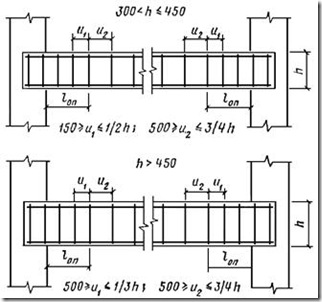
Rice. 90. Location of transverse reinforcement in beams without bends
3.108. The distances between transverse rods (clamps) in beams with compressed longitudinal reinforcement taken into account in the calculation should be taken according to table. 25 of this Guide.
3.109. In knitted frames of the middle beams of monolithic ribbed floors, including multi-span continuous ones, monolithically connected at the top by a slab along the entire length, with temporary loads on the floor of 3 tf/m2 or less, it is recommended to install open clamps. Closed clamps are installed in separate (not monolithically connected to the slab) beams of rectangular or T-section, in the outer beams of monolithic ribbed floors, in beams with calculated compressed reinforcement, as well as in the middle beams of monolithic ribbed floors designed for a live load of more than 3 tf/m 2.
3.110. In beams with knitted reinforcement designed for torsion, closed clamps should be installed with their ends overlapping by 30 d, and for welded frames, vertical and horizontal transverse rods must be welded in accordance with clause 2.34a of this Manual.
3.111. Connections of longitudinal and transverse rods in welded beam meshes must provide anchorage for transverse reinforcement, for which the welded connections must be of equal strength.
In knitted frames, the clamps must be designed in such a way that longitudinal rods must be located in the bridges of their bend, as well as the bend of the end hooks (in the absence of bypass of the ends).
It is recommended that each clamp cover no more than five tension rods and no more than three compression rods in one row. With a larger number of rods in one row, as well as with a beam width of 350 mm or more, it is recommended to switch to four-shear or multi-shear clamps.
The clamp designs used for beams with knitted reinforcement are shown in Fig. 1 and 85. In this case, the width of the four-shear clamp, depending on the number of rods in one row of the beam and the number of rods between the internal branches of the clamps, is determined according to table. 29. 
3.112. For monolithic structures, transverse reinforcement of the beam should not be installed in the thickness of the supports at the intersection of the beam with the column or with the girder. In such structures, the first clamp or transverse rod should be placed in the span at a distance of 50 mm from the edge of the support.
When supporting monolithic beams on brickwork on the outer support, the first clamp or transverse rod is placed at the end of the beam with the necessary protective layer, and within the middle supports, the installation of clamps continues with the step taken for the span of the beam.
In prefabricated beams, the placement of transverse reinforcement should begin from the end of the element, taking into account the protective layers of concrete.
3.113. Bent rods should be used in beams reinforced with knitted frames if the calculation requires transverse reinforcement. It is not recommended to use bent rods in welded frames.
The length of the support section of the beam on which the bends are placed is determined by calculation.
The radius of the arc along which the inclined section of the rod is bent must be at least 10 d.
The angle of inclination of the bend to the longitudinal axis of the beam, as a rule, should be taken equal to 45°. In beams with a section height of more than 800 mm and in beam-walls, the angle of inclination of the bends can be increased to 60°, and in low beams and in beams designed for concentrated loads - reduced to 30 ° .
3.114. It is preferable to form inclined reinforcement by bending the lower span reinforcement onto supports, which in continuous beams is then transferred through the support to the adjacent span (see Fig. 87).
If there is a need to increase the number of inclined rods on an intermediate support beyond the number that can be obtained by bending rods from adjacent spans, then short rods with two inclined sections should be installed above this support (rod d k in fig. 87) and with two horizontal sections at the bottom to provide anchoring.
The use of short bars with one inclined section and so-called floating bars not connected to the general reinforcement, as well as bars with a complex configuration having more than two inclined sections, is not allowed.
3.115. In beams with a section width of 200 mm or less, it is allowed to bend one rod in each plane. In beams with a section width of 300 - 400 mm, at least two rods should be bent in the first plane from the support, and in subsequent planes it is allowed to bend one rod at a time. In beams with a section width of more than 400 mm, bending less than two rods in each plane is not allowed.
If the diameters of the bending rods are different, then bends of larger diameters should be located closer to the support.
It is recommended to place the bends of the rods symmetrically relative to the vertical axis of the beam section. If one rod is bent in a section, it should be placed along the axis of symmetry of the section or as close as possible to it. It is not recommended to bend the rods located directly at the side surfaces of the beam; they should be placed at a distance of at least 2 d from the side faces of the beam (Fig. 91).
3.116. The distances between the inclined sections of the rods along the length of the beam are determined by calculation. If the calculation does not give instructions on the location of the planes of the bends, then the distances between them are taken according to Fig. 87.
3.117. The rods of the first bend plane from the support are not taken into account in the calculation as part of the above-support longitudinal reinforcement. The section from which the upper straight section of the bent rod of each plane is fully included in the work on the supporting bending moment is considered to be the section at a distance of ³ from the top point of the inclined section of this rod towards the support. Similarly, the lower straight section of the bent rod is completely excluded from the work on the span bending moment in the section at a distance ³ from the bottom point of the inclined section towards the span (here h 0 - design height of the beam section, approximately equal to 0.9 - 0.95 of the height of the beam section).
3.118. Rods bent out of the span in the first and second planes from the intermediate support must be inserted into the adjacent prologue, and those bent in the third and subsequent planes are allowed to be torn off if there is no need for them to work on the supporting bending moment or if it is difficult to place them in the supra-support section in the span above (see Fig. 87).
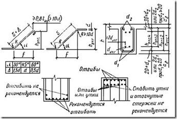
Rice. 91. Design of bent rods
3.119. The upper ends of bent rods that do not pass through the support and adjacent span must end in straight sections with a length of at least 0.8 l an, adopted in accordance with the instructions of clause 2.40 of this Guide, but not less than 20 d in stretched and 10 d in a compressed area. Breakage of the bent rod in the stretched area (bottom) should be avoided. In beams with a height of more than one meter, a bent rod made of smooth reinforcement can end in a compressed zone only with a hook without a straight section (see Fig. 91), and periodic profile bars must always have a straight section.
3.120. Vertical projections h o tg. i mm, inclined sections of bent rods depending on the height of the beam section h b and the size of the protective layer of concrete A b, are calculated using the following formulas:
![]() ; (20)
; (20)
In this case: - for secondary beams; mm - for main beams, which are adjacent to secondary beams with upper reinforcement with a diameter of up to 20 mm; mm - for main beams, which are adjacent to secondary beams with upper reinforcement with a diameter of more than 20 mm.
If d 2 > 20 mm, or d 1 > 20 mm, or ( d 1 + d 2) > 40 mm, then formulas (21), (22) and (23) should be substituted accordingly ( d 2 , d 1 instead of 20 or d 1 + d 2 instead of 40; h o tg. i calculated with an accuracy of 10 mm.
Additional instructions for reinforcing beams in areas where concentrated loads are applied
3.121. In sections of beams where concentrated loads are applied, including in places where monolithic secondary beams rest on the main ones, additional reinforcement should be provided according to Fig. 92. The cross-sectional area of this reinforcement is determined by calculation.
Additional reinforcement, depending on the type of main reinforcement, is designed in the form of welded mesh, bends, hangers or quickened clamps. In this case, the number of welded meshes, bends or hangers must be at least two; there must be at least 4 Æ 6 vertical rods in each welded mesh; bends or hangers must have a diameter of at least 10 mm; bent rods must have a horizontal straight section in the upper zone with a length of at least 0.8 l an, adopted according to clause 2.40 of this Guide, and not less than 20 d, and if the bends are made of smooth reinforcement, this section should end with a hook.
MONOLITHIC FRAMES
3.122. Issues of designing racks of monolithic frames are reflected in the “Columns” section of this Manual.
Issues of designing crossbars for monolithic frames are reflected in the “Beams” section of this Manual.
The most critical part of monolithic frames are the nodes in which it is necessary to create the rigidity required by the calculation. When designing assemblies of monolithic frames, usually saturated with reinforcement, one must strive to ensure maximum convenience laying and compaction concrete mixture, to the possibility of using vibrators. For the convenience of placing the reinforcement in the assembly, the cross-sectional width of the rack should be 50 - 100 mm larger than the cross-sectional width of the crossbar.
3.123. In the assemblies of monolithic frames, the elements are usually mated at right angles. In this case, the crossbar can be connected to the end of the rack or within its height. The upper crossbar of the frames is sometimes made with a broken outline. The design of such a crossbar in the fracture zone has some specifics, since this unit must be rigid, i.e. framed
3.124. It is recommended to pair the crossbar at right angles with the end of the rack according to Fig. 93. The rods reinforcing the reentrant corner must be mutually inserted into the adjacent element of the assembly, as a rule, without bending. The longitudinal working rods of the rack are brought to the top of the crossbar (taking into account the protective layer of concrete). The lower bars of the span reinforcement of the crossbar are inserted into the rack beyond its inner edge to an amount that ensures anchoring. The transverse rods (clamps) of the rack are brought to the top of the crossbar, and the transverse rods (clamps) of the crossbar are brought to the inner edge of the rack.
The rods reinforcing the outgoing corner (external rods) are designed depending on the magnitude of the design forces and eccentricity acting in the node longitudinal force. The upper rods of the crossbar support reinforcement are inserted into the rack and, depending on the amount of reinforcement, i.e. depending on the calculation, they are cut off in one or two sections, with no more than four rods in the first section, and no less than two rods in the second section. The break locations are shown in Fig. 93. With significant eccentricity, part of the outer rods of the rack, but at least two, can be passed into the crossbar by the amount l an from the inner edge of the rack.
When using welded reinforcement in the crossbar and in the rack, it is recommended to install special support meshes or frames in the nodes according to the type of reinforcement for the supports of the main beams. If it is impossible to install welded reinforcement, the assembly is reinforced with separate rods.

Rice. 92. Additional reinforcement of beams in places of concentrated loads
A- welded mesh; b- pendants; V- increasing the frequency of clamps
3.125. It is recommended to reinforce the interface of the crossbar with the intermediate section of the rack according to Fig. 94. In this case, the longitudinal reinforcing bars of the rack of the lower floor should be released above the ceiling (above the crossbar) for the installation of knitted or welded joints with the reinforcing bars of the rack of the upper floor.
l an. In this case, the node is designed according to Fig. 94, A, if the distance to the outer rods of the rack is greater than the required anchorage length, or according to Fig. 94, b, if the distance to the outer rods of the rack is less than the anchorage value. In the latter case, additional clamps with a pitch of no more than 100 mm must be installed on the bent sections of the rod to prevent the rod from unbending. It is recommended to bend the rods in the second row in relation to the external reinforcement of the rack. If it is impossible to bring the upper crossbar rods to the required anchorage length, the assembly can be designed according to Fig. 94, V reinforced with an anchor washer.
If alternating bending moments act in the supporting section of the crossbar and, therefore, the lower rods can be stretched, they must be inserted into the rack, ensuring the appropriate anchorage length, or the anchorage must be strengthened with a washer at the end.
If the lower compressed reinforcement of the crossbar is taken into account in the calculation, then it should be inserted beyond the inner edge of the rack by the amount l an, as for compressed rods, in accordance with clause 2.40 of this Manual.
3.126. The construction of a broken crossbar depending on the mating angle is carried out according to Fig. 95.
It is recommended to anchor the intersecting longitudinal reinforcement bars of the tension zone of the section of the incoming corner of the broken beams in the compressed zone of the section. It is allowed to break off some of these rods, but do not put them into a compressed area.
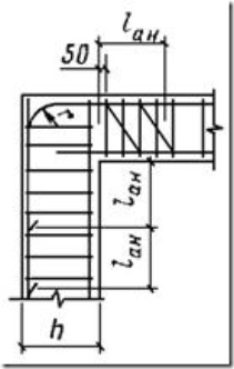
Rice. 93. Reinforcement of the uppermost nodes of monolithic frames
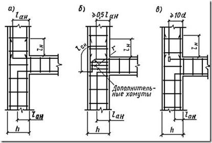
Rice. 94. Reinforcement of the interface between the intermediate crossbar and the stand
A- in the case when the distance to the external reinforcing bars of the rack is greater l an; b- the same if the distance is less l an; V- option of strengthening the anchoring of stretched crossbar rods with a washer

Rice. 95. Scheme of reinforcement of the broken crossbar interface
A- at a mating angle less than 160°; b- the same, greater than 160°
On a section of length it is necessary to install transverse reinforcement with a cross-sectional area Fа.х is not less than that determined by the formula
![]() ,
,
Where F a 1 - cross-sectional area of longitudinal tensile rods, unanchored in the compressed zone;
F a 2 - the same, anchored in a compressed zone.
When connecting crossbar elements with a broken outline at an angle of less than 160°, it is not allowed to lay stretched solid rods below the outline of the angle. On the contrary, it is recommended to lay solid rods on top in the compressed area. Joining compressed rods at the vertex of an outgoing corner is not allowed.
When mating crossbar elements with a broken outline at an angle of 160° or more, both the upper and lower rods can be solid and follow the outline of the angle.
PLATES
3.127. Slabs are considered to be bendable structures of relatively small thickness and relatively large dimensions in plan, designed, as a rule, to absorb a load distributed over the area of the slab.
In design practice reinforced concrete structures Mostly there are beam slabs, supported along the contour, and cantilever slabs. They are made single-span or multi-span continuous, and they can be freely supported or clamped on supports.
Beam slabs are extended slabs with a slab aspect ratio of more than two and must be supported on opposite sides.
Contour supported slabs are those that are supported on two adjacent, three or four sides and have an aspect ratio of 2 or less.
Cantilever slabs are slabs that are embedded on one side into a wall or other structure, or that are part of a single- or multi-span slab hanging over an early support.
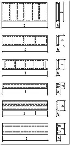
Rice. 96. Examples of precast slab designs
The slabs are made prefabricated and monolithic, and they can be elements of coverings, floors, slab foundations, retaining walls or other structures and are designed smooth or together with beams (ribs) of the corresponding structures.
Prefabricated slabs can be used for the same structural elements and be performed smooth or together with ribs. Instructions for designing the ribs of ribbed precast and monolithic slabs are given in the beam design section of this Manual.
Examples of prefabricated slab designs with ribs are shown in Fig. 96. Examples of monolithic slab designs are given in this section.
3.128. The thickness of monolithic slabs must be assigned in accordance with clause 3.1 of this Guide and accepted no less than:
10 mm - for coatings;
15 mm - for interfloor ceilings of residential and public buildings,
20 mm - for interfloor ceilings of industrial buildings.

The minimum thickness of prefabricated slabs should be determined from the conditions for ensuring the required thicknesses of protective layers of concrete and the conditions for the location of reinforcement along the thickness of the slab.
3.129. The thickness of the concrete protective layer for the working reinforcement of slabs under normal operating conditions must meet the requirements of paragraphs. 3.3; 3.4; 3.5; 3.6 and accepted according to table. 30 of this Guide.
The ends of the longitudinal working rods that are not welded to the anchoring parts must be spaced from the end of the slab at a distance of at least:
100 mm - for prefabricated floor slabs and wall panels span up to 12 m inclusive;
150 mm - for monolithic slabs up to 6 m long inclusive;
200 mm - for monolithic slabs longer than 6 m.
3.130. Plates, as a rule, must be reinforced with welded mesh.
Knitted reinforcement can be used for relatively small monolithic areas prefabricated floors and monolithic slabs with a large number of disordered holes, as well as in cases where the use of welded reinforcement is not allowed under operating conditions in accordance with App. 2.
The diameter of the working rods for welded reinforcement of slabs is recommended to be at least 3 mm, and for knitted reinforcement - at least 6 mm.
3.131. The distances between the axes of the working reinforcement rods in the middle part of the slab span (at the bottom) and above the support (at the top of multi-span slabs) should be no more than: 200 mm - with the thickness of the slab h h - with slab thickness h³ 150 mm.
The distances between the rods brought to the slab support should not exceed 400 mm, and the cross-sectional area of these rods per meter of slab width should be at least 1/3 of the cross-sectional area of the rods in the span, determined by calculation based on the greatest bending moment.
3.132. The cross-sectional area of the working reinforcement of the slabs is determined by calculation and must meet the requirements of clause 3.8 of this Manual. The diameter and pitch of the rods of this reinforcement can be selected according to the table. 31.
The cross-sectional area of the distribution reinforcement in beam slabs must be at least 10% of the cross-sectional area of the working reinforcement at the point of the greatest bending moment. It is recommended to assign the diameter and pitch of the rods of this reinforcement, depending on the diameter and pitch of the rods of the working reinforcement, according to the table. 32.
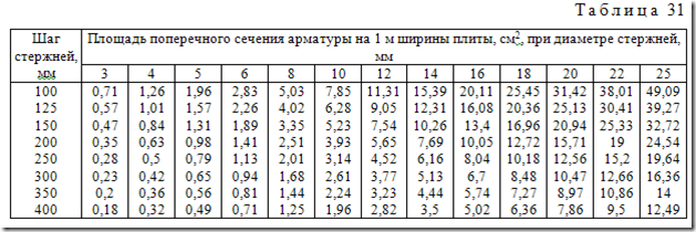
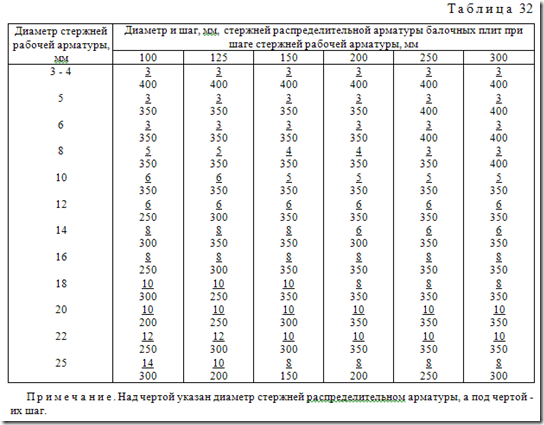
3.133. Beam monolithic slabs, reinforced with welded mesh, it is recommended to design according to Fig. 97, 98.
It is recommended to construct the span reinforcement of slabs up to 3 m wide and up to 6 m long in the form of a flat, solid welded mesh, the transverse rods of which are the working reinforcement of the slab (Fig. 97, A).
When the diameter of the working reinforcement is more than 10 mm, the slab can be reinforced with flat, narrow welded unified mesh. The length of such meshes must correspond to the width of the slab, which in this case can be more than three meters. The longitudinal rods of these grids are the working reinforcement of the slab, and the transverse ones are distribution reinforcement, overlapped in the slab without welding (see paragraph 2.52 of this Manual). The supporting reinforcement of continuous slabs can be designed according to Fig. 97, V in the form of two, with a shift, grids (Fig. 98, V) or one (Fig. 98, G) mesh with transverse working rods laid along the supports. These support meshes can be rolled.
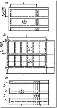
Rice. 97. Scheme of reinforcement of monolithic beam slabs with welded mesh (plans)
A- span reinforcement in the form of solid welded mesh with transverse working rods; b- the same, in the form of narrow welded mesh with longitudinal working rods; V- plan of supporting reinforcement
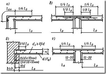
Rice. 98. Reinforcement of slab supports with welded mesh (cuts in working direction)
A- the outermost support of the slab, monolithically connected to the reinforced concrete beam; b- extreme support of the slab on brick wall; V, G- the middle support of the slab, monolithically connected to a reinforced concrete beam, with supporting reinforcement from two spread meshes and from one mesh
Multi-span beam monolithic slabs up to 100 mm thick with working reinforcement for middle spans and supports with a diameter of up to 7 mm are recommended to be reinforced with welded rolled standard mesh with longitudinal working reinforcement according to Fig. 99. In this case, the rolls are rolled out across the secondary beams, and the transverse rods of the mesh, which are the distribution reinforcement of the slab, are overlapped without welding. In extreme spans and on the first intermediate supports, where rice is usually required. 99), which starts in the first intermediate support in the second span by 1/4 of the slab span. Instead of an additional mesh, it is possible to lay individual rods tied to the main mesh.

Rice. 99. Continuous reinforcement of monolithic continuous slabs with welded rolled mesh
A- plan and sections of a slab supported on reinforced concrete beams; b- detail supporting the slab on a brick wall
3.134. It is recommended to reinforce slabs supported along the contour with welded mesh. In this case, slabs having dimensions of no more than 6´3 m are allowed to be reinforced in the span with one solid welded mesh with working reinforcement in both directions. With a large number of identical slabs with a smaller span of 2.5 - 3 m, in order to save reinforcing steel, it is recommended to reduce the number of rods on the outer strips of the slab compared to the middle ones. In this case, the slab can be reinforced with one solid flat welded mesh with the amount of reinforcement required on the outer strip, and an additional mesh is laid on the middle section of the slab (Fig. 100). Edge width l k is determined by calculation.
If it is not practical to reinforce the slab with solid welded mesh, it is permissible to construct reinforcement from narrow welded unified mesh with longitudinal working reinforcement. The grids are laid in a span in two layers in mutually perpendicular directions (Fig. 101). In this case, meshes with shorter working rods (Fig. 101, item 2) are laid in the bottom layer. The mounting rods of the meshes of each layer are placed end-to-end and not joined, and in the meshes of the lower layer they should be at the bottom, in protective layer working reinforcement, and in the meshes of the upper layer - from above.
Above-support reinforcement of continuous multi-span slabs supported along the contour (Fig. 101, b) with flat meshes in the spans is designed similarly to the supporting reinforcement of beam slabs according to Fig. 98.
Multi-span continuous slabs supported along the contour, designed for a uniformly distributed load with working reinforcement with a diameter of up to 7 mm, can be reinforced with standard rolled meshes with longitudinal working rods (Fig. 102). To do this, the slab should be divided into three stripes in each direction: two outer strips of 1/4 of the smaller span and a middle one. Rolls in spans are laid in two layers, rolled out in a mutually perpendicular direction only along the middle strips of the slabs (Fig. 102, A). In this case, the supporting reinforcement of the corners of the slab can be designed in the form of square flat meshes with working rods in both directions. These grids are laid at the intersection of the ribs of the slabs, and the rods can be parallel to the ribs or laid at an angle of 45° to them (Fig. 102, b).

Rice. 100. Scheme of reinforcement of a slab span supported along the contour with solid welded mesh
1 - main grid; 2 - additional mesh
3.135. It is recommended to design knitted reinforcement for monolithic slabs with a thickness of 120 mm or less according to Fig. 103 without bends and bring all spanning lower rods to the supports, and install your own reinforcement above the supports (items 1, 2 Fig. 103), the so-called separate reinforcement. In this case, it is recommended to design the lower span working rods of continuous slabs through, passing them through several supports, and in the outer spans, if necessary according to calculation, additional rods are installed (item 4, Fig. 103).
Above-support reinforcement in the non-working direction should be installed structurally in an amount of at least 1/3 of the cross-section of the working reinforcement in the span.
In slabs of large thickness, in order to save reinforcement, it is recommended to bend part of the span rods onto supports (the so-called continuous reinforcement). The rods are bent at an angle of 30° in slabs up to 150 mm thick and at an angle of 45° in slabs with a thickness of 160 mm or more. Bends in slabs with continuous reinforcement are designed according to Fig. 104.

Rice. 101. Scheme of reinforcement of a slab supported along the contour with narrow welded mesh
A- span grids; b- support meshes
3.136. It is recommended to design knitted reinforcement of slabs supported along the contour in the same way as knitted reinforcement of beam slabs. At the same time, to save reinforcing steel, the slab can be divided into three strips in each direction - two outer strips with a width of 1/4 of the smaller span and a middle one. In the outer strips, the cross-sectional area of the reinforcement can be halved compared to that parallel to them middle zone, but not less than three rods per meter. The rods in the direction of the short side are laid at the bottom. Above-support working reinforcement is installed evenly along the entire length of each side of the slab.

Rice. 102. Scheme of reinforcement of a slab supported along the contour with welded rolled mesh
A- span and middle support reinforcement; b- support reinforcement for slab corners
3.137. On the outer supports of slabs monolithically connected to reinforced concrete purlins, the supporting design reinforcement should be embedded in the purlin to the anchoring depth accepted in accordance with clause 2.40 of this Manual.
On the outermost free supports of the slabs, the span reinforcement should be placed beyond the edge of the support in accordance with clause 2.42 of this Manual.
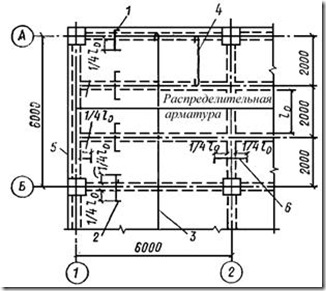
Rice. 103. Separate reinforcement of monolithic beam slabs with separate rods (knitted reinforcement)
1, 2 - pressure fittings in the working direction; 3 , 4 - span reinforcement in the working direction; 5 , 6 - support valves in the non-working direction

Rice. 104. Continuous reinforcement of monolithic slabs with individual rods (knitted reinforcement)
A- middle support (reinforced concrete beam) of a multi-span slab; b- the same, steel beam; V- extreme support - reinforced concrete beam; G- the same, brick wall; 1 - bends; 2 - span fittings; 3 - additional support reinforcement (installed if there are not enough bent rods)
Reinforcement of monolithic slab supports with individual rods under different support conditions is shown in Fig. 105, 106, 107.
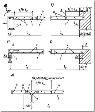
Rice. 105. Separate reinforcement of the outer supports of monolithic slabs with separate rods in the working direction
A b V- freely lying on steel beam, G- the same, on a brick wall; d 1 F a diameter d; 2 - support reinforcement (according to calculation, but not less than 0.5 F a), 3 - support reinforcement at least 1/3 F a and not less than 5 Æ 6 AI per 1 linear m, 4 - distributed fittings; 5 6 - a rod that ensures the joint operation of the slab with a steel beam, usually, if not required by calculation - Æ 6 step 1000; 7 - welding

Rice. 106. Separate reinforcement of the outer supports of monolithic slabs with separate rods in the non-working direction
A- freely lying on a steel beam; b- cantilevered on a steel beam; V- monolithically connected to a reinforced concrete beam; G- pinched in a brick wall; d- adjacent to the wall without support; 1 - span working fittings F and in diameter d; 2 F a; 3 - support reinforcement; 4 5 - fittings reinforced concrete beam

Rice. 107. Reinforcement of the middle supports of a monolithic slab with separate rods
A- monolithically connected to the reinforced concrete beam in the working direction; b- freely lying on the steel beam in the working direction; V- monolithically connected to the reinforced concrete beam in the non-working direction; 1 - span working fittings F a diameter d; 2 - distribution fittings; 3 - support reinforcement according to calculation, but not less than 1/3 F a; 4 - reinforced concrete beam reinforcement; 5 - welding
3.138. Cantilever slabs with a cantilever overhang of up to one meter are assumed to have a constant thickness, and when overhanging more than one meter, the cross-section of the cantilever slab can be variable: at the free end of the cantilever - at least 50 mm, and at the embedment site - according to calculation.
The depth of embedding of the cantilever slab into the wall is determined by calculation and, for a temporary load of up to 400 kgf/m2, must be no less than:
250 mm - with console overhang up to 600 mm;
380 mm - with a console overhang of 600 - 1000 mm.
When the console extends over 1000 mm or under heavy loads, it is necessary to take special measures to anchor the console in the wall.
3.139. Cantilever slabs are usually reinforced only with upper reinforcement. Consoles, which are part of a single- or multi-span slab, are reinforced together with the latter and the same reinforcement - meshes or separate rods.
When reinforcing cantilever slabs with an overhang of more than 1000 mm, it is allowed (if it is rational from the point of view of unifying the position and grids) to break half of the working rods at half the overhang of the cantilever.
3.140. It is recommended to reinforce thick monolithic slabs (for example, foundation slabs) with welded reinforced concrete blocks of the type shown in Fig. 21.
They should be installed with a gap equal to the width of the reinforced concrete block, and horizontal flat welded mesh from which the reinforced concrete block is assembled should be placed in the gap. If necessary, welded mesh in a perpendicular direction is also laid.
Holes in slabs
3.141. Large holes in reinforced concrete slabs, panels, etc. must be bordered by additional reinforcement with a cross-section no less than the cross-section of the working reinforcement (of the same direction), which is required by the calculation of the slab as continuous (Fig. 108, A).
Holes up to 300 mm in size are not framed with special rods. The knitted working and distribution reinforcement of the slab around such holes is thickened - two rods are placed with a gap of 50 mm (Fig. 108, b). When reinforcing a slab with welded mesh, it is recommended to cut such a hole in the reinforcement locally.
Holes (openings), if necessary by calculation, are framed with reinforced ribs. The dimensions and reinforcement of these ribs depend on the size, shape, location in plan relative to the floor beams, purpose of the opening and in each special case are decided by the designer based on calculations.
In reinforcement drawings, special rods for reinforcing the slab within the size of the hole, with the exception of the bordering ones, are usually not given, and a note should be placed on the drawing: within the hole, the rods should be cut in place and bent into the body of the slab.
When reinforcing the floor with welded mesh, holes up to 500 x 500 mm in size are not taken into account when laying out the mesh, and a note is given on the drawing: cut the hole in place.
For larger mesh opening sizes, the mesh openings are laid out taking into account the holes, however, in the area of the opening, it is recommended to reinforce the slab with separate rods without disturbing the unification of the mesh.
l n according to clause 2.46 of this Guide.

Rice. 108. Reinforcement of slabs at holes
A- holes larger than 300 mm; b- holes up to 300 mm in size; 1 - slab reinforcement bars; 2 - border rods formed by thickening the reinforcement of the slab; 3 - rods of special reinforcement bordering the hole
Reinforcement of slabs in the punching zone
3.142. Transverse reinforcement installed in slabs in the punching zone must have anchoring at the ends, performed by welding or wrapping around the longitudinal reinforcement. The distance between the transverse rods is taken to be no more than 1/3 h and no more than 200 mm, where h- thickness of the slab. The width of the area for placing transverse reinforcement must be at least 1.5 h.
COLORS
3.143. Floors can be ribbed, frequently ribbed, so-called coffered, beamless, etc. Depending on the method of work, floors can be prefabricated, monolithic, or prefabricated-monolithic.
Rules for the design of prefabricated floors from typical elements are determined by the corresponding standard series.
3.145. When designing prefabricated monolithic floors, to ensure conditions for the manufacture of structures, durability and joint operation of reinforcement and concrete, the design requirements set out in this Guide, as well as the following recommendations, must be met.
To increase the industrialization of the manufacture and installation of prefabricated monolithic structures, it is advisable to use large prefabricated elements and place in them the main part of the working longitudinal tensile reinforcement.
3.146. On the surfaces of precast elements in contact with additionally laid concrete, dowels, roughness of contact surfaces, longitudinal projections and grooves should be installed in accordance with the calculated or design requirements release fittings.
Surface roughness can be achieved naturally (unsmoothed concrete) and artificially(notching, peeling of the surface layer, chemical method and etc.).
Keys (Fig. 109) and mates shown in Fig. 110, it is recommended to install on surfaces where it is difficult to obtain natural roughness (for example, on surfaces in contact with the formwork).
Reinforcement outlets, as a rule, should be a continuation of clamps, transverse rods of welded frames, and longitudinal working reinforcement (Fig. 111). In order not to complicate the production of prefabricated elements, it is recommended to produce reinforcement, if possible, from surfaces free from formwork. The released rods must be securely anchored in the additionally laid concrete.

Rice. 109. Keys
A- triangular; b- rectangular; 1 - prefabricated element; 2 - additionally laid concrete

Rice. 110. Interfaces of prefabricated elements with additionally laid concrete
a - crossbar with slabs; b- slabs between each other; 1 - prefabricated element; 2 3 - longitudinal projection or groove

Rice. 111. Releases of reinforcement from prefabricated elements
A- transverse; b- longitudinal
3.147. When placing reinforcement in additionally laid concrete, it is necessary to provide gaps between the reinforcement and the surface of the precast element, as well as between the rows of reinforcement of adjacent precast elements, ensuring that the joints are filled with concrete or mortar and the reinforcement is protected from corrosion.
3.148. In prefabricated monolithic structures, on the supports of which as a result of embedding joints (welding reinforcement outlets; laying additional reinforcement in the seams between elements covering the joint; installing reinforced concrete elements over the joined structures covering the joint, etc.) (Fig. 112 - 114) negative support moments may occur, it is recommended to assign the cross-sectional area of the supporting reinforcement in accordance with the current regulatory documents on the calculation of statically indeterminate reinforced concrete structures taking into account the redistribution of forces. The breakage points of this reinforcement are determined in accordance with clause 3.40 of chapter SNiP II-21-75.

Rice. 112. Pairing beams and slabs
1 - main beam; 2 - secondary beam; 3 - plate; 4 - fittings releases

Rice. 113. Pairing plates
1 - crossbar; 2 - additionally laid concrete; 3 - plate; 4 - releases of reinforcement from slabs; 5 - support fittings
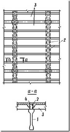
Rice. 114. Prefabricated monolithic covering of a one-story industrial building
1 - crossbar; 2 - additionally laid concrete; 3 - plate; 4 - fittings releases
3.149. When designing prefabricated floors, provision must be made for the installation of joints between individual elements filled with concrete. The width of the joints is determined based on the condition of ensuring high-quality filling and should be at least 20 mm for elements with a section height of up to 250 mm and at least 30 mm for elements of greater height.
In this case, it must be possible to place abutting reinforcement or embedded parts and their reliable welding.
3.150. To embed joints of prefabricated reinforced concrete structures, the design grade of concrete should be set depending on the operating conditions of the elements being connected, but should not be lower than M100.
To seal hard-to-reach or hard-to-control joints, it is recommended to fill the joint with mortar or concrete under pressure, as well as the use of expanding cement.
3.151. Beamless floors are designed according to Fig. 115.

Rice. 115. Reinforcement scheme for beamless floors
A- span reinforcement - narrow welded mesh; b- the same, pressure fittings; V- span reinforcement - separate rods; G- the same, pressure fittings
Slabs with lower working reinforcement with a diameter of 10 - 12 mm and a shorter side length of 2.5 - 3 m should be reinforced with flat standard welded solid mesh. For large slab widths and rod diameters greater than 12 mm, it is recommended to use narrower meshes laid in two mutually perpendicular layers.
In the upper part of the columns, in the places where they interface with the slab, beamless floors are equipped with widenings - capitals or capitals with capital slabs.
3.152. Reinforcement of beamless floors with individual rods is usually done without bends. With a large number of identical slabs, in order to save reinforcement, the floor is divided into span and above-column strips (see Fig. 115, V, G). In both strips, the lower rods must be moved from the span axis in each direction by at least 0.35 l. In this case, in the above-column strip, the rods must be inserted beyond the edge of the capitals by at least 10 d. The rods of the upper reinforcement of the above-column strip must be inserted beyond the axis of the row of columns in each direction also by at least 0.35 l.
Separate instructions for the design of basement elements
3.153. The design of a monolithic interface between the basement wall and the bottom is carried out according to Fig. 116.
F A, f a - cross-sectional area, respectively, of all the upper support rods of the crossbar inserted into the wall and one rod of the wall;
l an is the anchorage length of the wall rods, taken in accordance with clause 2.40 of this Guide.
If the wall and crossbar rods are made of reinforcing steel of the same class, then
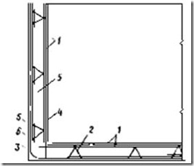
Rice. 116. Reinforcement of walls and bottoms of basements (pits, etc.)
1 - grids; 2 - supporting frame; 3 - corner (bent) mesh; 4 - butt mesh; 5 - reinforced block; 6 - concreting seam
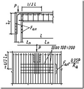
Rice. 117. Scheme of reinforcement of the junction of the floor crossbar with the basement wall
RETAINING WALLS
3.155. Retaining walls are designed to hold bulk soil in a vertical position.
The design of retaining walls is usually of an angle section made of smooth slabs or slabs with ribs (buttresses). Smooth vertical walls used at a relatively low height of retained soil - up to approximately 4 - 4.5 m. At higher heights, it is recommended to install buttresses in the wall on the ground side.
Horizontal slabs of corner walls are made smooth or with a so-called spur, that is, a network with an edge protruding down along the entire horizontal slab.
3.156. Retaining walls can be made monolithic or prefabricated.
Smooth vertical elements of monolithic retaining walls corner type usually designed with variable thickness. In this case, the thickness at the top is assigned to be at least 100 mm, and at the bottom it is taken according to calculation. Horizontal slabs are also made, as a rule, of variable thickness.

Rice. 118. Scheme of reinforcement of retaining walls with self-supporting reinforcement blocks
A- with separate concreting of the base and wall; b- with simultaneous concreting of the base and wall; 1 - reinforcement block; 2 - corner working butt mesh; 3 - flat butt mesh; 4 - concreting seam
3.157. The thickness of the protective layer of concrete for the working reinforcement of retaining walls in the absence of groundwater is taken for vertical elements to be no less than the diameter of the working reinforcement and not less than 30 mm, and for horizontal slabs - as in foundations (see paragraph 3.26 of this Guide).
3.158. Reinforcement of retaining walls with a height of 3 m or more is recommended to be carried out with spatial reinforcement frames (Fig. 118).
3.159. To save reinforcing steel when constructing smooth extended retaining walls, it is recommended to reinforce the vertical slabs of these walls in two zones. In this case, a mesh with vertical working reinforcement, which is required in the upper zone, is installed over the entire height of the wall. In the lower zone, an additional mesh is installed, also with vertical working rods. The cross-sectional area of the working reinforcement in both grids is set in accordance with the requirements for calculating the lower zone of the wall. The section where the vertical reinforcement bars of the lower grids break is determined by calculation.
Horizontal slabs, as a rule, are reinforced with meshes without breaking the rods. For an example of reinforcement of a smooth retaining wall, see Fig. 119.
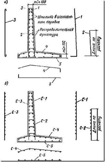
Rice. 119. Scheme of reinforcement of a monolithic smooth retaining wall
A- piecework rods; b- welded mesh; 1 - 5 - reinforcing bars; S-1 - S-5 - welded mesh
Note. Rod pos. 3 and mesh C-3 should be installed when the mesh thickness is more than 150 mm
3.160. Monolithic retaining walls with ribs (buttresses), as a rule, are made with constant thickness vertical horizontal plate. These slabs are constructed according to the rules for the design of slabs supported on three sides, which are set out in the “Slabs” section.
The ribs are reinforced with longitudinal (inclined working and lateral vertical structural rods) and transverse (horizontal clamps) reinforcement in the form of separate rods or welded mesh. An example of a retaining wall with buttresses is shown in Fig. 120.
Rice. 120. An example of designing a monolithic retaining wall with buttresses
A- support grids; b- span networks; V- buttress reinforcement; 1 - knitted reinforcement; 2 - welded mesh
TUNNELS
3.161. The tunnels are intended for underground laying various communications and are divided into pass-through and non-pass-through. By production method construction work they can be prefabricated or monolithic.
Prefabricated reinforced concrete tunnels can be constructed as composites of individual elements - walls, bottom and lid; from elements of a U-shaped section - a bottom with lower sections of walls and a floor with upper sections of walls, or from elements that are one wall with sections of a bottom and a floor. The cutting can be done according to another, economically justified scheme.
At small sizes cross-section (from the point of view of ease of manufacture and transportation), tunnels can be constructed from solid closed blocks 1 - 3 m long.
When constructing monolithic tunnels, which are always closed frames, it is necessary to assign reinforcement and joints of rods, taking into account the maximum convenience of construction work.
3.162. It is recommended to reinforce tunnels with self-supporting spatial frames and bent meshes (Fig. 121). For joining distribution (anti-shrinkage) reinforcement, standard meshes can be used in accordance with current GOSTs.
The frames are assembled from meshes and supporting devices that fix the meshes in working position and provide overall spatial rigidity (Fig. 122).
When reinforcing tunnels in which only the bottom slab is initially concreted, special bent joint meshes should be provided to connect the wall frames to the bottom.
Reinforcement of tunnel sections with a complex configuration (places of various junctions, angles of rotation, etc.) can be carried out with flat and bent meshes.
3.163. Elements of prefabricated tunnels are reinforced with solid composite meshes or frames and are equipped with reinforcement outlets or embedded parts for connection with adjacent elements.
3.164. Reinforcement of monolithic tunnels with individual rods is shown in Fig. 123.

Rice. 121. Scheme of tunnel reinforcement with self-supporting reinforcement blocks
A- section of the tunnel; b- layout of corner grids along the tunnel; 1 - reinforced block; 2 - corner mesh; 3 - butt mesh; 4 - concreting seam
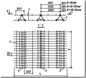
Rice. 122. Self-supporting spatial frame (reinforced block)
1 - grids; 2 - frame supporting clamps

Rice. 123. An example of reinforcement of a monolithic tunnel with individual rods
1 - 5 - numbers of fittings positions
4. DESIGN FEATURES OF REINFORCED CONCRETE STRUCTURES SUBJECT TO DYNAMIC LOADS
4.1. Dynamic loads, in terms of the nature of the impact on the structure, can be periodic and pulsed, and in terms of repeatability, they can be repeatedly repeated and slightly repeated.
Periodic dynamic refers to a load with a force amplitude of more than 100 kgf/s.
An impulse load includes a load with an equivalent instantaneous impulse value of more than 100 kgf/s.
Repeated loads include loads in which the structure experiences more than 10 6 cycles of force impacts, and the coefficient of operating conditions of the reinforcement m a1
4.2. When designing reinforced concrete structures exposed to dynamic loads, in addition to the instructions given in Section. 1 - 3, follow paragraphs. 4.3 - 4.21.
4.3. The outlines of reinforced concrete structures designed for the loads specified in clause 4.1 should be taken as simple: without sudden changes in elevations, without breaks in elements and sudden changes in sections. In places where structural elements meet (for example, a crossbar with a column), as well as changes in the cross-sections of elements by more than 1.5 times, as a rule, it is necessary to install haunches, rounding of incoming corners, etc. It is recommended to make the holes round, and if it is necessary to make a rectangular hole, its corners should be rounded.
4.4. For reinforced concrete elements designed to withstand dynamic loads, it is recommended to use a design grade of concrete not lower than M200; for heavily loaded elements (for example, for columns that bear significant crane loads, frame elements of foundations for cars, etc.) - not lower than M300. Mounting concrete on the top of the structure should be made of concrete of a grade not lower than M200.
4.5. To reinforce elements of reinforced concrete structures exposed to dynamic loads, the reinforcement specified in clause 1.11 should be used, taking into account the instructions in clause 1.14 of this Guide.
When choosing design reinforcement, preference should be given to reinforcement class A-I II.
The use of AC-II class reinforcement is more effective in structures exposed to repeated loads with a cycle asymmetry coefficient ρ a
In structures subject to repeated loads, the use of reinforcement is allowed classes B-I and Vr-I.
For transverse reinforcement of linear elements, reinforcement of classes A-II and A-I should generally be used for structural and installation reinforcement.
4.6. Steel for the construction of embedded parts in structures subject to dynamic loads should be used in accordance with App. 3.
4.7. Welding of reinforcement and embedded parts of structures subject to dynamic loads should be carried out taking into account the instructions for welding connections of reinforcement and embedded parts of reinforced concrete structures.
4.8. When joining stretched bars with an overlap in the bypass area, it is necessary to install additional transverse reinforcement in accordance with clause 2.49 of this Manual.
4.9. Concrete areas that receive impulses of the magnitude specified in clause 4.1 must have indirect reinforcement in accordance with clause 3.53 of this Guide. In this case, the indirect reinforcement meshes must be knitted from reinforcement classes A-I or A-II, with a diameter of 12 - 14 mm.
4.10. Minimum area cross-section of longitudinal reinforcement μ, % cross-sectional area of concrete in reinforced concrete elements structures subject to repeated loads, the following is accepted:
μ = 0.2% - for reinforcement A of beams, slabs and other bent, as well as eccentrically stretched elements; μ = 0.25% - for reinforcement A and A I columns and other eccentrically compressed elements. When exposed to several repeated loads, the value of μ.
4.11. The distances between longitudinal rods in slabs, beams, columns and other structures, as well as stirrups (transverse rods) in columns should not exceed 300 mm.
4.12. The distances between the lateral reinforcement bars of the beams (Fig. 89) should not exceed 300 mm. Minimum diameter of these rods at the height of the beam h£ 1500 mm 12 mm, at higher heights - 16 mm.
4.13. Reinforcement of crossbars and beams exposed to repeated loads with a cycle asymmetry coefficient ρ a
4.14. Columns in all cases are reinforced with symmetrical reinforcement, and every 3 to 5 rods should be wrapped with clamps or studs.
4.15. The sealing of working reinforcement of crossbars and beams in a colony should be provided according to the type of rigid frame units.
4.16. In the case of using welded frames, all connections of longitudinal and transverse rods must have standardized strength.
4.17. Under intense dynamic loads, enhanced transverse reinforcement of reinforced concrete frame units should be provided (Fig. 124).

Rice. 124. An example of reinforcement of the interface between a reinforced concrete beam and a column under intense dynamic influences
1 - column reinforcement; 2 - crossbar fittings; 3 - additional vertical rods; 4 - additional horizontal clamps
additional clamps and rods with a diameter of 8 - 10 mm, respectively, with a pitch of 70 - 100 mm, as well as reinforced transverse reinforcement in adjacent sections of the crossbars and columns with a pitch half as large as required for static loads, but not more than 100 mm.
4.18. Along free edges massive structures anti-shrinkage reinforcement should be installed from class A-I steel from rods with a diameter of 12 mm for the thickness of the slab h n £ 1.5 m; 16 mm at 1.5 h p h p ³ 3 m.
Reinforcement is also performed in the form of meshes or frames. The reinforcement spacing in both directions is assigned to 200 - 300 mm.
4.19. Regardless of the calculation requirements, all openings with a side size of more than 300 mm should be bordered with anti-shrink reinforcement from rods with a diameter of 12 mm made of class A-I steel, embedded in the array by the amount l n.
4.20. When determining the dimensions of the supporting surfaces of structures that absorb dynamic loads from equipment, the distance from the edge of the wells anchor bolts to the outer edge of the structure should be taken: for bolts with a diameter of up to 35 mm - at least 100 mm and for bolts with a larger diameter - at least 150 mm.
In addition, when using bolts with anchor plates, the distance from the bolt axis to the edge of the structure should be taken equal to at least four bolt diameters. If this condition cannot be met, additional reinforcement is installed between the bolt and the face of the structure.
4.21. If the embedded part is designed to withstand alternating loads, provision should be made for the installation of lap anchors that work in axial tension separately in each of these directions, as well as the installation of thrust plates or rods (Fig. 125).

Rice. 125. Embedded part under shear dynamic alternating load
1 - steel plate; 2 - normal anchor; 3 - inclined anchor; 4 - stop made of steel plate


