Backfilling of foundation cavities. Backfilling work
09.12.2016
This process involves filling the depressions that were left during the construction of the foundation of the house with soil.Why is this necessary?
Backfill is prerequisite for competent construction. It serves several purposes:- Protects the foundation from destruction
- Maintains the strength of the entire building structure
- Provides waterproofing and insulation of the base
For backfilling, it is advisable to use the soil that was dug during the construction of the foundation. Using sand or a sand mixture will significantly reduce the quality of the backfill.
It should be noted that backfilling is carried out only after the foundation has completely hardened, which will take at least two weeks in dry and warm weather. Often builders neglect these standards because they want to finish the project as quickly as possible. This must not be allowed under any circumstances. Neglecting technology can lead to such sad consequences as deformation and destruction of the foundation, as well as violation of waterproofing.Backfill process
When filling the foundation of a building, be sure to strictly follow the instructions of the specialists.The soil must not only be poured into the hole, but also compacted properly. At the same time, soil moisture and density must meet certain standards. You can find out the necessary indicators for a specific area by contacting the geological service.
Humidity standards
If the soil at the construction site does not meet moisture standards, it should be moistened. It is necessary to wet the soil until it begins to meet the following indicators:- 8-12% for silty sands
- 9-12% for silty and light sandy loams
- 12-17%, if the building site is dominated by light loams
- 16-23% - acceptable standards for heavy soils
Dry soil is thoroughly moistened. To do this, they do not use water, but a specially prepared solution, which experts call clay or cement “milk.” It is very simple to make by adding a small amount of dry cement or clay to water.
Stages of backfilling the foundation
After the soil is properly prepared, backfilling occurs directly. The procedure consists of two stages.- The first stage involves gradually filling voids near the foundation and compacting the soil. During the process, it is necessary to ensure that no foreign objects get into the ground. Elements of organic origin are especially dangerous, since after rotting, voids can form in the soil, which will lead to its settlement and possible deformation of the foundation.
- The second stage is the construction of the blind area. The blind area removes excess moisture from the house during rainfall. It is performed at a slight angle to the building and fits tightly to it, without any gaps. If backfilling is done correctly, the blind area will not bend or sag, and will provide reliable protection home from moisture and freezing.
Foundation backfill technology
Backfill the foundation big building manually is very difficult. For uniform backfilling and high-quality compaction, special equipment is used, such as a compaction machine. It provides the necessary soil density and performs work much faster than workers.If the building is no different large sizes, you can do without technology. When manually backfilling, compaction is carried out in several layers, every 30 cm of soil. Particular attention should be paid to the places where communications pass. Wires and pipes should not be under a layer of soil exceeding 20 cm. The earth near them is compacted less tightly to avoid damage.
When constructing any building, it should be remembered that proper backfilling of the foundation guarantees its integrity. Therefore, you should not neglect this important event if you want to have a durable and durable house!
THE GOVERNMENT OF MOSCOW
COMPLEX OF PERSPECTIVE
CITY DEVELOPMENT
TR 73-98
MOSCOW - 1998
« Technical recommendations using soil compaction technology with backfill pits, trenches, sinuses" were developed by candidates of technical sciences V. M. Goldin, L. V. Gorodetsky, engineer V. F. Demin (road construction laboratory of NIIMosstroi) with the participation of Mosstroylicensiya. The technical recommendations summarize the experience construction organizations HC "Glavmosstroy", JSC "Mosinzhstroy" on soil compaction when filling pits, trenches, cavities, as well as digging up the roadway. Technical recommendations have been agreed upon with JSC "Mosinzhstroy", the Gordorstroy trust, the design institute "Mosinzhproekt".
1. GENERAL PROVISIONS
1.1. Technical recommendations apply to soil compaction work when backfilling pits, trenches, cavities after laying underground utility networks, installation of foundations of buildings under construction.1.2. Technical recommendations also apply to soil compaction work after restoration of underground utility networks in the roadway area. 1.3. Soil compaction should be carried out in accordance with SNiP 3.02.01-87 “Earth structures, foundations and foundations” and VSN 52-96 “Instructions for production earthworks V road construction and during the installation of underground utility networks.”1.4. Characteristics, terms and definitions of soils are used in accordance with GOST 25100-95 “Soils. Classification".2. TECHNOLOGY OF SOIL COMPACTION WHEN BACKBILLING PITS
2.1. Permission to backfill pits with soil is given by a commission consisting of the work manufacturer, the customer and the author of the project, simultaneously with the preparation of an act for hidden work. 2.2. The required soil density when backfilling pits is assigned by the project based on data from a soil study using the standard compaction method, at which it is installed optimal humidity and maximum density, which must be at least 0.95.2.3. To determine the basic properties of the soil, it is necessary to be guided by the technical conclusion of Mosgorgeotrest on the engineering and geological conditions of the construction site.2.4. Soil compaction should be done when its natural moisture content is optimal. Table 2.1 shows the optimal soil moisture content and permissible humidity deviations ("overmoistening" coefficient).Table 2.1.
Natural soil moisture should be determined according to GOST 5180-84.2.5. If the moisture content of cohesive soils is insufficient (the content of clay particles is more than 12%), they should be moistened in the development areas, and non-cohesive soils (the content of clay particles is less than 3%) can be moistened in the backfill layer. If there is excessive soil moisture, it should be dried. 2.6. Backfilling of soil or sand under the base of the floors along the bottom of the finished pit of the underground part of the building is carried out using jib cranes equipped with grabs, leveling the soil along the bottom of the pit and compacting it with rammers.2.7. Machines and mechanisms for soil compaction should be selected taking into account the properties and condition of the soil being compacted (moisture, uniformity, granulometric composition), the required degree of compaction, the volume of work and the pace of their implementation (clause 2.9, table 4.1). The placement of machines for backfilling pits is carried out in accordance with the project for the construction of a specific building.2.8. Backfilling of pits is carried out using jib cranes equipped with grabs, excavators such as EO-2621V-3, EO-3123, EO-4225, etc. layer by layer. 2.9. Compaction of the backfilled soil in pits is carried out using hydraulic hammers of the SP-62, SP-71, RAMMER type, vibrating plates DU-90, DU-91, and electric rammers IE-4502A. In Fig. Figure 2.1 shows a diagram of backfilling soil under floors in the basement of a building. 2.10. The average thickness of the poured soil layer when using hydraulic hammers and vibrating plates should be for: sand - 70 cm; sandy loam and loam - 60 cm; clay - 50 cm. When using electric rammers type IE-4502A, the thickness of the poured layer should be no more than 25 cm. 2.11. To achieve the density of compacted soil up to TO= 0.95 compaction time for one track with hydraulic hammers should be 15 seconds. When using vibrating plates and electric rammers, the number of passes (impacts) should be 3 - 4. Each subsequent pass (impact) of the compacting machine should overlap the track of the previous one by 10 - 20 cm. 2.12. Present the completed soil compaction work to the author's and technical supervision and draw up a report for hidden work.3. TECHNOLOGY OF SOIL COMPACTION WHEN BACKBACKING SINUSES
3.1. Before backfilling the sinuses with soil, the following work must be completed: installation of structures for the underground part of buildings; cleaning construction waste; waterproofing; drainage.3.2. The required density of sandy soil when filling the sinuses must be at least TO = 0,98.Rice. 2.1. Scheme for backfilling soil under floors in the basement of a building:
a) prefabricated foundations, b) pile foundations;
1 - prefabricated foundation with an installed column; 2 - zone of soil compaction using manual electric rammers; 3 - soil compaction zone mechanical tampers; 4 - building wall; 5 - reinforced concrete grillage; 6 - driven pile. B - take according to the table. 3.13.3. The sinuses are filled in layers using excavators, leveling excavators, and bulldozers. In this case, the thickness of the sand layer should be no more than 70 cm; for sandy loam and loam - 60 cm, for clay - 50 cm. 3.4. Compaction of the backfilled soil in the sinuses is carried out with hydraulic hammers of the SP-62, SP-71, “RAMMER” type, and vibrating plates DU-90, DU-91.3.5. To achieve the density of compacted soil up to TO= 0.98 compaction time for one trace should be 20 seconds. 3.6. The soil is compacted, starting from areas near the building structures, and then moving towards the edge of the slope, with each subsequent pass of the tamping machine must overlap the trace of the previous one by 10 - 20 cm (Fig. 3.1). 3.7. When working to compact soil near the structures of a building under construction, utility service entry points and other hard-to-reach places, electric rammers of the IE-4505, IE-4502A type should be used. In this case, the thickness of the poured layer should be no more than 25 cm and the number of passes should be no less than 4.3.8. The marks of the top layer of compacted soil must strictly comply with the design.3.9. Submit the completed work to the author's and technical supervision and draw up a report for hidden work.3.10. Recommended machines and mechanisms for soil compaction when backfilling pits and cavities in confined spaces are listed in Table. 3.1.

Rice. 3.1. Scheme of backfilling the pit cavity:
1 - blind area; 2 - building wall; 3 - vertically installed expanded clay concrete slab; 4 - manual soil compaction zone; 5 - foundation slab; 6 - horizontally laid expanded clay concrete slab; 7 - drainage pipe; 8 - boundary of filling the drainage with sand; 9 - soil layers, compacted light mechanical tampers; p.p. - basement floor; h 1 - h n- the thickness of the poured soil layer is assumed to be up to 0.25 m Note. Expanded clay concrete slabs can be replaced with polymer materials in accordance with VSN 35-95 “Instructions for the technology of using polymer filter shells to protect underground parts of buildings and structures from flooding with groundwater.”
Table 3.1.
|
Type and brand of compacting machines and mechanisms |
Weight of compacting machines and mechanisms ( m), kg |
Ratio of masses of building structures (M) and compacting machines and mechanisms (t), kg |
|||||
|
M £ m |
M£5 m |
M£10 m |
|||||
|
The minimum distance from compacting machines and mechanisms to building structures b and thickness of the poured soil layer h o, cm |
|||||||
| Hydraulic hammers (mounted on excavators): | |||||||
| GPM-120 | |||||||
| GPM-150 | |||||||
| GPM-300 | |||||||
| SP-71 A | |||||||
| SP-71 | |||||||
| SP-62 | |||||||
| Pneumatic hammers (mounted on excavators): | |||||||
| PN-1300 | |||||||
| PN-1700 | |||||||
| PN-2400 | |||||||
| Electric rammers: | |||||||
| IE-4504 | |||||||
| IE-4502A | |||||||
4. TECHNOLOGY OF SOIL COMPACTION WHEN BACKBILLING TRENCHES
4.1. Backfilling of utility trenches is carried out after testing them and drawing up a report, insulating joints, channels, niches and obtaining permission to carry out backfilling.4.2. Backfilling of trenches for underground communications with soil must be carried out after the laying of pipelines and network devices; it is also necessary to take measures against their axial displacement and against damage to pipelines and their insulation. The scheme for soil compaction during backfilling of trenches, the scheme for organizing work on backfilling trenches and the scheme for backfilling trenches are shown in Fig. 4.1, 4.2, 4.3 respectively.4.3. Backfilling of trenches with laid underground utilities is carried out in two steps. First, the sinuses are filled and lined manually and the pipelines are sprinkled to a height above the top of the pipeline of at least 0.2 m with careful layer-by-layer manual tamping, and in winter for ceramic, asbestos-cement and polyethylene pipes - 0.5 m. Then the rest of the trench is filled up by carefully dumping soil with bulldozers. 4.4. Layer-by-layer compaction of pipeline backfill is carried out mainly using pneumatic, motor, electric tampers, as well as the vibration compaction method.4.5. The sinuses between the pipe and the walls of the trench are filled in layers with EO-3532A leveling excavators, EO-2621B, EO-3123, EO-4225 excavators, etc.; the thickness of the layer should be no more than 0.25 m. Compaction is carried out evenly on both sides with electric tampers of type IE-4502A.4.6. When compacting the soil above communications, the thickness of the protective layer must be at least 0.25 m for metal and reinforced concrete pipes and at least 0.4 m for ceramic, asbestos-cement and plastic pipes. The protective layer over communications is also compacted with electric tampers.4.7. When laying cable lines, the trenches must be backfilled at the bottom and backfilled with a layer of fine earth that does not contain stones or construction waste on top. The thickness of the sand layer for backfill and the thickness of the backfill layer must be at least 0.1 m.
Rice. 4.1. Scheme of soil compaction when filling trenches:
1 - zone above the pipeline where soil compaction is prohibited; 2, 3 - thickness of the soil layer compacted by manual mechanisms; 4 - layer of soil compacted with hand-held, non-mechanized tools; 5 - layers of soil compacted with mechanical tampers (accepted up to 0.25 m); h 1,2,3 - thickness of the compacted layer, compaction should be carried out simultaneously on both sides Note. Hand-held non-mechanized tools - shovel, scoop, wooden tampers; manual mechanisms - platform vibrators, electric rammers, mechanical rammers
Rice. 4.2. Scheme of organization of work on backfilling trenches:
a) excavator-planner; b) bulldozer;
1 - excavator-planner; 2 - backfilling of soil with a bulldozer; 3 - backfilling of soil with a leveling excavator; 4 - leveling the soil with a leveling excavator; 5 - leveling the soil manually; 6 - polyvinyl chloride pipe; 7 - soil for backfilling; 8 - bulldozer; 9 - sewer well The distance from the trench slope line to the beginning of the soil dump along the edge of the trench must be at least 0.7 m with a trench depth of up to 3 m and at least 1.0 m with a trench depth of more than 3 m.
Rice. 4.3. Scheme for backfilling trenches:
a) telephone sewer; b) ductless heating network;
1 - soil layers compacted with manual electric rammers; 2 - layers of soil, filled and compacted manually; 3 - plastic pipes; 4 - drainage pipe (pipe filter or other); 5 - pipelines; I - soil layers compacted with light mechanical compactors; II - soil layers compacted with manual electric rammers; III - layers of soil, filled and compacted manually 4.8. When backfilling pipelines laid in trenches with a slope of more than 20°, it is necessary to take measures against soil sliding and erosion storm water. The method of strengthening must be indicated in the work design. 4.9. When laying polyethylene pipes, the bottom of the trench is leveled, and rocky soils it is necessary to arrange a cushion of loose soil with a thickness of at least 0.1 m without including stones, crushed stone, etc. 4.10. Backfilling of polyethylene pipelines must be done in the coldest time of the day only after preliminary testing for density.4.11. Further backfilling of soil above the laid pipelines is carried out using excavators, leveling excavators, and bulldozers in layers with a layer thickness of 0.7 m for sand, 0.6 m for sandy loam and loam, 0.5 m for clay. Layer-by-layer soil compaction is carried out using hydraulic hammers and vibrating plates.4.12. Backfilling a trench with soil using a bulldozer is shown in Fig. 4.4. The figure shows that the area of the dump from which the soil is taken is divided into separate, sequentially developed sections. The bulldozer approaches the edge of the dump from its end at a certain angle, picks up soil in area I and, after moving it into the trench, moves to the next area II. The soil from sections II, IV, VI is moved into the trench by transverse passages of the bulldozer, and from sections I, III, V, VII - by oblique passes. This method of work reduces the length of passages of a loaded bulldozer and improves soil collection conditions.

Rice. 4.4. Backfilling trenches with soil using a bulldozer:
1 - bulldozer; 2 - pipeline
4.13. When passing the route along buildings, fences, green spaces, backfilling of trenches is done manually with layer-by-layer compaction of the backfill every 0.2 m.4.14. Trenches and pits at intersections with existing or planned roads must be filled to the full depth with sand and compacted to K pack- 0.98.4.15. Seal upper layers 1.0 - 1.2 m from the surface can be produced with trailed rollers for T-150 (SD-801) tractors and self-propelled different types weighing 6 - 15 tons (DU-47B, DU-64, DU-58A, etc.)4.16. At the intersections of trenches with existing underground communications (pipelines, cables, etc.) running within the depth of the trenches, the design must provide devices that ensure the unchangeable position and safety of communications during the period of work and operation. If such devices are not provided, backfilling of trenches should be carried out in the following order: backfilling under existing communications is carried out with sand along the entire cross-section of the trench to a height of up to half the diameter of the pipeline (cable) or its protective shell with layer-by-layer compaction; along the trench, the size of the bedding at the top should be 0.5 m larger on each side of the pipeline (cable) or its protective shell, and the steepness of the slopes of the bedding should be 1: 1.4.17. Present the completed soil compaction work to the author's and technical supervision and draw up a report for hidden work.4.18. Backfilling and compaction of pits, trenches, and cavities over which rail tracks are to be constructed for the installation of tower cranes should be done in the same way as the construction of a foundation made of bulk soil.4.19. The fill soil of the subgrade should be laid in layers with mandatory layer-by-layer compaction. The thickness of the layers is determined by the machines and mechanisms used to compact the soil. 4.20. Density (volumetric weight of the skeleton) of soil roadbed in g/m 3 should be no less for: fine and dusty sands - 1.7; sandy loam - 1.65; loams - 1.6; clay - 1.5. 4.21. When installing rail tracks with wooden sleepers, the density of the soil should be checked every 12.5 m, and when constructing tracks with reinforced concrete beams - under each beam. 4.22. The results of the inspection must be recorded in the act of putting the rail track into operation. 4.23. Recommended machines and equipment for backfilling pits, trenches, cavities, and soil compaction are given in Table. 4.1.
Table 4.1.
|
Name of machines, equipment |
Brand, type |
Execution of technological processes |
| Hydraulic excavators | EO-2621V-3 EO-4245 EO-4225A EO-3123 and others. | |
| Hydraulic hammers for excavators | "Ronson" "Rammer-700" "Rammer-1600" SP-62; SP-71 | Soil compaction in pits, trenches, cavities |
| Vibrating plates | DU-90; DU-91 | |
| Electric rammers | IE-4502A IE-4505 | |
| Bulldozers | DZ-42; DZ-162-1; DZ-190 and others. | Backfilling of pits, trenches, cavities |
| Excavator-planners | EO-3532A UDS-114 | Backfilling and distribution of soil in trenches and cavities |
| Rollers | DU-54M DU-47B DU-64 DU-58A and others. | Compacting the top layers of soil in trenches |
Table 4.2.
4.26. For layer-by-layer compaction of backfills, the following methods are recommended: for non-cohesive soils - vibration and vibration tamping; for loosely cohesive soils - rolling, compacting, vibrating tamping, vibrating; for cohesive soils - rolling, compacting, vibrating tamping and combined.4.27. Soil compaction in cramped conditions when backfilling places where sheet piling elements are removed should be done using special compaction agents of static, vibration or impact action, which make it possible to obtain a compaction coefficient of at least 0.98.4.28 to the entire depth. The process of compacting the backfilled soil in places where the elements of sheet piling connections are dismantled should be carried out using installations equipped with devices that control the degree of layer-by-layer compaction.4.29. In the conditions of Moscow, installations such as: static probing S-832, static and dynamic action UGB-IBCM, dynamic action TsBP-15m can be used.5. TECHNOLOGY OF SOIL COMPACTION AFTER REPAIR OF UNDERGROUND ENGINEERING NETWORKS IN THE ROAD ROAD AREA
5.1. Restorative repairs are carried out after a hole in the roadway associated with the repair, laying and re-laying of underground structures, as well as destruction caused by natural or other phenomena. Restoration work can be carried out taking into account subsequent reconstruction, therefore restoration repair is divided into: primary (temporary); repeated (final).5.2. Temporary restoration repairs are limited to the short period of its implementation and its final implementation. The city’s administrative bodies monitor this and must take the necessary measures to carry out the final refurbishment road surfaces. In Moscow, a large number of excavations of sections of roadways are carried out annually, and their high-quality restoration is necessary.5.3. The work area associated with the excavation and restoration of the roadway must be fenced. The type of fences, their illumination at night, and the installation of traffic control signs for public transport are determined in each specific case by the Moscow State Traffic Inspectorate. 5.4. The Association of Administrative and Technical Inspections of Moscow issues a warrant to carry out work to eliminate the holes, indicating the time frame for the final restoration of the road surface. 5.5. Backfilling of trenches is carried out after laying pipelines, testing them, drawing up a report and obtaining permission to carry out backfilling. Backfilling of the trench must be carried out taking measures against damage to pipelines and their isolation from discharged sand, as well as against displacement of pipelines from the axis and includes the following stages: backfilling and compaction of sand in the pits for butt joints; tamping of the sinuses between the pipe and the bottom of the trench; backfilling , leveling and compaction of sand in the cavity between the pipe and the walls of the trench; backfilling, leveling and compaction of the protective layer and upper layers. 5.6. The cavities between the pipe and the bottom of the trench are tamped with hand tampers. The gaps between the pipe and the walls of the trench are filled in layers with excavators and bulldozers, the layer thickness should be no more than 25 cm, compaction is carried out evenly on both sides with electric tampers. When compacting sand over communications, the thickness of the protective layer must be at least 25 cm for metal and reinforced concrete pipes and at least 40 mm for ceramic, asbestos-cement and plastic pipes. The protective layer over communications is also compacted with electric tampers and vibrators. Further filling of sand is carried out by excavators, bulldozers layer by layer with a layer thickness of up to 30 cm and compacted by self-propelled rollers weighing 6 - 15 tons. 5.7. In the summer, the compacted sand base is generously filled with water, and after water is absorbed into the sand and excess water is removed along the longitudinal slope of the trench, additional compaction is carried out with self-propelled rollers, 4 to 6 passes along one track. This technology for backfilling and compacting sand makes it possible to obtain a soil compaction coefficient in the trench within the range of 0.98 - 1.0. A road base is laid on the compacted sandy base within the excavation area, on which an asphalt concrete coating is laid. IN winter time years top layer 10 - 15 cm thick sand base made from hot sand. In Fig. 5.1 shows a diagram of work to restore the road structure.
Rice. 5.1. Sequence of work to restore the road structure
5.8. On main streets of citywide and regional significance, trenches are filled with sand and compacted in accordance with paragraphs 5.5, 5.6, 5.7 of these recommendations. The top layer of the trench to be filled to a depth of 30 - 40 cm should be made from factory-made crushed stone mixtures, the composition of which is presented in table. 5.1.
Table 5.1.
|
Mix type |
|||||||
|
not less than 0.05 |
|||||||
| Coarse I | |||||||
| Same II | |||||||
| Medium grain I | |||||||
| Same II | |||||||
6. SEALING QUALITY CONTROL
6.1. When constructing trenches, pits and cavities, control over the quality of soil compaction must be organized during the work process and after its completion. During the work process, the type of soil used and the correctness of its filling, the degree of density and moisture content and the uniformity of soil compaction must be checked. 6.2. The type of soil used is determined by determining the particle size distribution and plasticity number. 6.3. The degree of density and moisture content of the soil is monitored by testing soil samples. This check is carried out on the filled layers at depths of 0.3; 0.5; 0.9; 1.2; 1.5 m from the top of the pit. The locations of the pits are marked: in trenches - along the axis of the trench every 50 m; in the axils of pits - along the perimeter of the foundations every 50 m, but not less than one at the ends of the building; in foundations for floors - one hole per 100 m 2.6.4. The degree of soil density is controlled by comparing the density of a sample taken without disturbing the structure from an embankment or trench with the optimal density of a given soil obtained by standard compaction. The degree of soil density is determined by the compaction coefficient " TO" Methods for determining the compaction coefficient " TO"(standard compaction method SoyuzDorNII, cutting ring method, density meter of the MGP "Condor" design) are presented in Appendix 1; 2; 3.6.5. When several construction organizations work together at a construction site, control over the quality of soil compaction is assigned to the general contractor and the technical supervision of the customer.6.6. In order to ensure high-quality compaction of sand in trenches falling into the roadway area, the central road laboratory of the Association of Administrative and Technical Inspections of Moscow or the road construction laboratory of NIIMosstroy determines the sand compaction coefficient and gives permission to work on restoring the road structure.7. SAFETY REQUIREMENTS
7.1. When carrying out work, it is necessary to comply with the requirements of SNiP III-4-80 “Safety in construction”, SNiP 3.02.01-87 “Earth structures, foundations and foundations” and VSN 52-96 “Instructions for excavation work in road construction and installation underground engineering networks."7.2. Persons over 18 years of age who have undergone a medical examination, special training, introductory instruction and workplace safety instruction are allowed to work on soil compaction.7.3. All used machines and devices must have passports and inventory numbers, according to which they are recorded in special log books and periodic inspections. Specially trained workers and maintenance personnel are allowed to operate construction machines and operate devices.7.4. Work areas on streets, driveways, courtyards, as well as in places where people or vehicles move, must be fenced protective barriers. Warning notices and signs must be installed on the fence, and at night the work site must be illuminated.7.5. Persons allowed to operate manual electric machines, must have II qualification group on safety precautions.7.6. When carrying out work, use only serviceable equipment and devices. 7.7. Excavation work in the area of active underground communications should be carried out under the direct supervision of a foreman or foreman, and in the security zone of live cables or an existing gas pipeline, in addition, under the supervision of electrical workers - or gas facilities. When unloading soil, place the dump truck no closer than 1 m from the edge of the trench. 7.8. Do not allow the presence of people, as well as other work, in the area of action of earth-moving machines. 7.9. One-sided backfilling of cavities of freshly laid retaining networks and foundations is allowed after measures have been taken to ensure the stability of the structure under the accepted conditions, methods and order of backfilling.7.10. Systematically monitor the condition of trench slopes, and if cracks appear, take measures against soil collapse.7.11. Systematically check the quality of soil compaction. Near structures, perform all work only during daylight hours.7.12. The descent of workers into the pit (trench) and their ascent must be carried out using ladders installed on the border of the danger zone for the passage of people when the machines are operating.8. ENVIRONMENTAL PROTECTION
8.1. It is necessary to carry out activities and work to protect the natural environment in accordance with the “Rules for organizing the preparation and production of earthen and construction work in Moscow" (Moscow Government Decree No. 207 of March 17, 1998).8.2. It is prohibited to use equipment for soil compaction that is a source of release of harmful substances into the atmospheric air and increased levels of noise and vibration.8.3. All areas of the territory where soil compaction is carried out - in trenches, pits, cavities - must be fenced in accordance with the construction plan or work plan.8.4. Household and utility rooms for workers and engineers in accordance with regulatory requirements. Places should be equipped for storing materials, structures, products and equipment, as well as for installing construction equipment.8.5. In the area of soil compaction work, the plant soil layer must be cut and stored in special designated areas, and the trees to be preserved must be fenced.8.6. Industrial and domestic wastewater generated at the construction site must be cleaned and neutralized in the manner prescribed by the construction organization project and the work execution project.8.7. After laying underground utility networks, filling trenches, pits, cavities with soil and then compacting it to the required density, the ground surface must correspond to the marks specified in the work plan.8.8. The entire area where soil compaction work was carried out in trenches, pits and cavities must be landscaped.8.9. To sow the lawn, mixtures of grasses should be used, in particular, a mixture of common grass, meadow grass, English ryegrass and red fescue.8.10. To landscape a property, significant attention should be paid to choosing the type of plant for green spaces. In this case, it is necessary to take into account the climatic, soil and hydrological conditions of the planting area, as well as the features of its planning and development. In the conditions of Moscow, trees with a dense crown should most often be used: linden, birch, maple, poplar, larch, and fruit trees: apple trees, cherries, pears; from shrub species you should use acacia, jasmine, lilac, etc. 8.11. On streets, driveways and sidewalks that have improved road surface, trenches and pits are developed in fastenings and covered layer by layer with sand. This work is carried out in the presence of representatives of the technical supervision of operating organizations, road services and designer's supervision of design organizations.ANNEX 1
Determination of soil density by probing using an extended hammer
1. The sounding method can be used to determine the density of sandy and sandy loam soils in the field.2. The method is based on the resistance of the soil to immersion of a standard circular punch with a diameter of 16 mm. The stamp is crushed using weights from a height of 300 mm.
Rice. 1. Extended hammer for determining soil density by probing method
3. The degree of soil density is determined in the range of optimal humidity or close to it.4. The striker (Fig. 1) consists of a rod with an end pin (stamp) 250 mm long (1), a guide rod 900 mm long (2), a weight weighing 2.5 kg (3), a restrictive ring (4), a screw (5 ) and handle (6).5. Soil testing is carried out as follows. The striker is installed vertically on the leveled ground surface. Then they lift the weight to the restrictive ring and drop it freely. This repeats as many blows as it takes to immerse the striker to a depth of 250 mm. At the same time they calculate total number blows. Using the calibration graph (Fig. 2), for a given type of soil, find the point corresponding to the obtained number of blows when the end pin of the elongated striker is fully buried. A vertical line is drawn from this point until it intersects with the curve, after which it is found on the vertical axis volumetric mass soil skeleton (soil density).

Rice. 2. Calibration graphs of the dependence of the number of blows on the degree of soil density within the limits of their optimal moisture content:
and for sandy soils; b) for sandy loam soils
APPENDIX 2
Control of embankment compaction using the cutting ring method
The main control over the compaction of the embankment during the work process is carried out by comparing the volumetric weight of the soil skeleton taken from the embankment (g sk.), with optimal density (g sk. op. Sampling and determination of the volumetric weight of the soil skeleton in the embankment is carried out using a soil sampler (Fig. 1), consisting of a lower part with a cutting ring and a hammer.
Rice. 1 . Soil selector:
a - the lower part of the soil sampler; b - cutting ring (separately); c - drummer with movable load
When taking a soil sample, the assembled soil sampler is placed on its cleaned surface and driven into the ground with a hammer. Then the cover and intermediate ring of the lower part of the sampler are removed, the cutting ring is dug in, carefully removed along with the soil, the soil is cut off with a knife flush with the lower and upper edges of the ring. The ring with soil is weighed with an accuracy of one gram and the volumetric weight of wet soil in the embankment is determined by the formula:
![]()
Where G 1 - mass of the ring, g; G 2 - mass of the ring with soil, g; V- ring compression, cm 3. This test is carried out three times. The moisture content of the tested soil sample is also determined three times by drying a sample of 15 - 20 g taken from each ring with soil to a constant weight. The volumetric weight of the embankment soil skeleton is determined by the formula:
![]()
Where W ow.- weight soil moisture in fractions of one. The resulting volumetric weight of the skeleton in the embankment is compared with the optimal density of the same soil. Coefficient TO, characterizing the degree of soil compaction in the embankment, is determined by the formula:
APPENDIX 3
Dynamic density meter DPU "Condor" universal for determining the quality of soil compaction
1 Universal dynamic density meter DPU “Condor” is designed for operational control quality of soil compaction during construction highways, airfields and other engineering structures.2. The DPU density meter is applicable in cases of sandy, sandy loam and loamy soils containing no more than 25% of solid particles larger than 2 mm.3. When using this density meter for express quality control of road construction work, it is required, in accordance with SNiP 2.06.03-85, at least 10% of all measurements should be carried out using standard methods, in particular for soils - by weight method with ring sampling (GOST 5180- 84).Density meter technical data
Weight of the device in packaging, kg 5
Cargo weight, kg 2.5
Load drop height, mm 300
Parameters of the pointed rod:
l, mm 300
Depth of controlled soil layer, mm 100 - 300
Density measurement limits (0.84 - 1.02) Ku
Density measurement error ±0.01 Ku
Construction and preparation for work
The basis of the DPU device for monitoring soil density (Fig. 1) is the working part, which includes a guide rod (1) with a handle (2), a load moving along the rod (3) and an anvil (4), which is struck by the falling load ( 3).When monitoring soil density, a rod with a conical tip (5) is screwed into the anvil (4) instead of a limiter.
Rice. 1. DPU device for monitoring soil density
Soil density control
1. The density meter is assembled according to the diagram (Fig. 1), when a rod with a conical tip is screwed into the anvil.2. The type of soil used is established based on the determination of the granulometric composition (GOST 12536-79) for non-cohesive soil, and in the case of cohesive soil, additionally, the plasticity number (GOST 5180-84).3. At the controlled object, an area of at least 30x30 cm in size is leveled, in the middle of which the first penetration is carried out. The penetrometer is installed strictly vertically to the soil surface and the rod is driven into the soil by blows of a weight to a depth of 10 or 20 cm, depending on the thickness of the poured soil layer. Then the rod is driven in with the number of blows determined to a depth of 20 or 30 cm. To obtain an average density value, penetration is repeated in two or three more places at a distance of at least 10 - 15 cm from the original probing site.4. The compaction coefficient of non-cohesive soils is determined according to schedule 1 based on the statistical average of 3 - 4 determinations, and for cohesive soils according to schedule 2. In the latter case, with a possible change in humidity from the optimal value, it is necessary to establish the natural moisture content of the soil by drying the sample in a temperature cabinet (thermostat) to get more exact values density. Humidity should be expressed in relative values, where W o- optimal soil moisture, determined using the SoyuzDorNII standard compaction method.

Schedule 1. Determination of the compaction coefficient of non-cohesive soils:
Medium and coarse sand (1), dusty sand (2)

Schedule 2. Determination of the compaction coefficient of sandy loam
|
1. General provisions. 1 2. Technology of soil compaction when backfilling pits. 1 3. Technology of soil compaction when backfilling sinuses. 2 4. Technology of soil compaction when backfilling trenches. 4 5. Soil compaction technology after restoration of underground utility networks in the roadway area. 8 6. Seal quality control. 9 7. Safety requirements. 9 8. Security environment.. 10 Annex 1 Determination of soil density by probing using an elongated hammer. eleven Appendix 2 Control of embankment compaction using the cutting ring method. 12 Appendix 3 The dynamic density meter DPU "Condor" is universal for determining the quality of soil compaction. 13 |
- Guidelines to determine the costs of construction of temporary buildings and structures, additional costs in the production of construction installation work in winter, costs of maintaining the customer-developer and technical supervision, other work and costs when determining the cost of construction products
- Methodological recommendations Methodological recommendations on the technology of using chemical additives in the production of prefabricated concrete and reinforced concrete structures for subways
- Recommendations Recommendations on the technology of using chemical additives in the production of monolithic concrete and reinforced concrete structures for tunnels and subways
- VSN 116-65 Technical instructions on the technology of construction and installation work for the electrification of railways (power supply device)
- Recommendations Methodological recommendations on the technology of constructing roadbeds from clayey soils of high humidity in the Non-Chernozem Zone of the RSFSR
- Recommendations Methodological recommendations on the technology of filling expansion joints of cement concrete pavements with bitumen-butyl rubber mastic using electric sealers of the "Joint" type
THE GOVERNMENT OF MOSCOW
COMPLEX OF PERSPECTIVE
CITY DEVELOPMENT
TR 73-98
MOSCOW - 1998
“Technical recommendations on the technology of soil compaction when backfilling pits, trenches, sinuses” were developed by candidates of technical sciences V. M. Goldin, L. V. Gorodetsky, engineer V. F. Demin (road construction laboratory of NIIMosstroi) with the participation of Mosstroylicensiya.
1. GENERAL PROVISIONS
1.3. Soil compaction should be carried out in accordance with “Earth structures, foundations and foundations” and “Instructions for excavation work in road construction and the installation of underground utility networks.”
1.4. Characteristics, terms and definitions of soils are used in accordance with “Soils. Classification".
2. TECHNOLOGY OF SOIL COMPACTION WHEN BACKBILLING PITS
2.1. Permission to backfill pits with soil is given by a commission consisting of the work manufacturer, the customer and the author of the project, simultaneously with the preparation of an act for hidden work.
2.2. The required soil density when backfilling pits is assigned by the project based on data from a soil study using the standard compaction method, which establishes its optimal moisture content and maximum density, which must be at least 0.95.
2.3. To determine the basic properties of the soil, it is necessary to be guided by the technical conclusion of Mosgorgeotrest on the engineering and geological conditions of the construction site.
2.4. Soil compaction should be done when its natural moisture content is optimal. The optimal soil moisture levels and permissible moisture deviations (the “overmoistening” coefficient) are given.
|
Soil name |
Optimal humidity, % |
Waterlogging coefficient |
|
Silty sands, light coarse sandy loams |
8 - 12 |
1,35 |
|
Sandy loam is light and dusty |
9 - 15 |
1,25 |
|
Heavy silty sandy loam, light silty loam and light silty loam |
12 - 17 |
1,15 |
|
Heavy loams and heavy silty loams |
16 - 23 |
1,05 |
Natural soil moisture should be determined by.
2.5. If the moisture content of cohesive soils is insufficient (the content of clay particles is more than 12%), they should be moistened in the development areas, and non-cohesive soils (the content of clay particles is less than 3%) can be moistened in the backfill layer. If there is excessive soil moisture, it should be dried.
2.6. Backfilling of soil or sand under the base of the floors along the bottom of the finished pit of the underground part of the building is carried out using jib cranes equipped with grabs, leveling the soil along the bottom of the pit and compacting it with rammers.
2.7. Machines and mechanisms for soil compaction should be selected taking into account the properties and condition of the soil being compacted (humidity, uniformity, granulometric composition), the required degree of compaction, the volume of work and the pace of their implementation (,). The placement of machines for backfilling pits is carried out in accordance with the project for the construction of a specific building.
2.8. Backfilling of pits is carried out using jib cranes equipped with grabs, excavators such as EO-2621V-3, EO-3123, EO-4225, etc. layer by layer.
3.7. When working to compact soil near the structures of a building under construction, utility service entry points and other hard-to-reach places, electric rammers of the IE-4505, IE-4502A type should be used. In this case, the thickness of the poured layer should be no more than 25 cm and the number of passes should be at least 4.
3.8. The marks of the top layer of compacted soil must strictly correspond to the design.
|
Type and brand of compacting machines and mechanisms |
Weight of compacting machines and mechanisms (m ), kg |
Ratio of masses of building structures (M) and compacting machines and mechanisms (t), kg |
|||||
|
M £ m |
M £ 5 m |
M £ 10 m |
|||||
|
Minimum distance from compaction machines and mechanisms to building structuresb and thickness of the poured soil layerh o , cm |
|||||||
|
b |
h o |
b |
h o |
b |
h o |
||
|
Hydraulic hammers (mounted on excavators): |
|||||||
|
GPM-120 |
275 |
||||||
|
GPM-150 |
345 |
||||||
|
GPM-300 |
1033 |
||||||
|
SP-71 A |
750 |
||||||
|
SP-71 |
750 |
||||||
|
SP-62 |
2100 |
||||||
|
Pneumatic hammers (mounted on excavators): |
|||||||
|
PN-1300 |
350 |
||||||
|
PN-1700 |
450 |
||||||
|
PN-2400 |
500 |
||||||
|
Electric rammers: |
|||||||
|
IE-4504 |
160 |
||||||
|
IE-4502A |
|||||||
3.11. The minimum distance from compaction machines and mechanisms to building structures, as well as the thickness of the poured layer of soil above the structures must be specified in the work plan.
4. TECHNOLOGY OF SOIL COMPACTION WHEN BACKBILLING TRENCHES
4.1. Backfilling of utility trenches is carried out after testing them and drawing up a report, insulating joints, channels, niches and obtaining permission to carry out backfilling.
4.2. Backfilling of trenches for underground communications with soil must be carried out after the laying of pipelines and network devices; it is also necessary to take measures against their axial displacement and against damage to pipelines and their insulation. A diagram of soil compaction during backfilling of trenches, a diagram of the organization of work for backfilling trenches, and a diagram of backfilling of trenches are shown in , , respectively.
4.3. Backfilling of trenches with laid underground utilities is carried out in two steps. First, the sinuses are filled and lined manually and the pipelines are sprinkled to a height above the top of the pipeline of at least 0.2 m with careful layer-by-layer manual compaction, and in winter for ceramic, asbestos-cement and polyethylene pipes - 0.5 m. Then the rest of the trench is backfilled by careful dumping of soil by bulldozers.
4.4. Layer-by-layer compaction of pipeline backfill is carried out mainly using pneumatic, motor, electric tampers, as well as the vibration compaction method.
4.5. The sinuses between the pipe and the walls of the trench are filled in layers with EO-3532A leveling excavators, EO-2621B, EO-3123, EO-4225 excavators, etc.; The layer thickness should be no more than 0.25 m. Compaction is carried out evenly on both sides using electric tampers of the IE-4502A type.
4.6. When compacting the soil above communications, the thickness of the protective layer must be at least 0.25 m for metal and reinforced concrete pipes and at least 0.4 m for ceramic, asbestos-cement and plastic pipes. The protective layer above the communications is also compacted with electric tampers.
4.7. When laying cable lines, the trenches must be backfilled at the bottom and backfilled with a layer of fine earth that does not contain stones or construction waste on top. The thickness of the sand layer for backfill and the thickness of the backfill layer must be at least 0.1 m.
4.26. The following methods are recommended for layer-by-layer compaction of backfills:
for non-cohesive soils - vibration and vibratory compaction;
for loosely cohesive soils - rolling, compacting, vibratory compaction, vibrating;
for cohesive soils - rolling, compacting, vibratory compaction and combined.
4.27. Compaction of soil in cramped conditions when backfilling places where sheet piling elements are removed should be done using special compaction agents of static, vibration or impact action, which make it possible to obtain a compaction coefficient of at least 0.98 to the entire depth.
4.28. The process of compacting the backfilled soil in places where the elements of sheet piling connections are dismantled should be carried out using installations equipped with devices that control the degree of layer-by-layer compaction.
4.29. In the conditions of Moscow, installations such as: static probing S-832, static and dynamic action UGB-IBCM, dynamic action TsBP-15m can be used.
5. TECHNOLOGY OF SOIL COMPACTION AFTER REPAIR OF UNDERGROUND ENGINEERING NETWORKS IN THE ROAD ROAD AREA
5.1. Restorative repairs are carried out after a hole in the roadway associated with the repair, laying and re-laying of underground structures, as well as destruction caused by natural or other phenomena. Restoration work can be carried out taking into account subsequent reconstruction, therefore restoration repair is divided into: primary (temporary); repeated (final).
5.2. Temporary restoration repairs are limited to the short period of their implementation and their final implementation.
The city’s administrative bodies are monitoring this and must take the necessary measures to carry out the final restoration of road surfaces in a short time. In Moscow, a large number of roadway sections of streets are excavated every year, and their high-quality restoration is necessary.
5.3. The work area associated with the excavation and restoration of the roadway must be fenced.
The type of fences, their illumination at night, the installation of signs regulating the movement of urban transport in each specific case is determined by the Moscow State Traffic Inspectorate.
5.4. The Association of Administrative and Technical Inspections of Moscow issues a warrant to carry out work to eliminate the holes, indicating the time frame for the final restoration of the road surface.
6.5. When several construction organizations work together at a construction site, control over the quality of soil compaction is assigned to the general contractor and the technical supervision of the customer.
6.6. In order to ensure high-quality compaction of sand in trenches falling into the roadway area, the central road laboratory of the Association of Administrative and Technical Inspections of Moscow or the road construction laboratory of NIIMosstroy determines the sand compaction coefficient and gives permission to work on restoring the road structure.
7. SAFETY REQUIREMENTS
7.1. When carrying out work, it is necessary to comply with the requirements of “Safety in construction”, “Earth structures, foundations and foundations” and “Instructions for excavation work in road construction and when installing underground utility networks”.
7.2. Persons over 18 years of age who have undergone a medical examination, special training, introductory instruction and workplace safety instruction are allowed to work on soil compaction.
7.3. All used machines and devices must have passports and inventory numbers, according to which they are recorded in special log books and periodic inspections. Specially trained workers and maintenance personnel are allowed to operate construction machines and operate devices.
7.4. Work areas on streets, driveways, courtyards, as well as in places where people or vehicles move, must be surrounded by protective barriers. Warning notices and signs must be installed on the fence, and at night the work site must be illuminated.
7.5. Persons allowed to operate manual electric machines must have qualification group II in safety precautions.
7.6. When carrying out work, use only serviceable equipment and devices.
7.7. Excavation work in the area of active underground communications should be carried out under the direct supervision of a foreman or foreman, and in the security zone of live cables or an existing gas pipeline, in addition, under the supervision of electricity or gas workers.
When unloading soil, place the dump truck no closer than 1 m from the edge of the trench.
7.8. Do not allow the presence of people or other work in the area of action of earthmoving machines.
7.9. One-sided backfilling of cavities in freshly laid retaining networks and foundations is permitted after measures have been taken to ensure the stability of the structure under the accepted conditions, methods and order of backfilling.
7.10. Systematically monitor the condition of trench slopes, and if cracks appear, take measures against soil collapse.
7.11. Systematically check the quality of soil compaction. All work near structures should only be performed during daylight hours.
7.12. The descent of workers into the pit (trench) and their ascent must be carried out using ladders installed on the border of the danger zone for the passage of people when the machines are operating.
8. ENVIRONMENTAL PROTECTION
8.1. It is necessary to carry out measures and work to protect the natural environment in accordance with the “Rules for organizing the preparation and production of earthworks and construction work in Moscow” (Moscow Government Decree No. 207 of March 17, 1998).
8.2. It is prohibited to use equipment for soil compaction that is a source of release of harmful substances into the atmospheric air and increased levels of noise and vibration.
8.3. All areas of the territory where soil compaction is carried out - in trenches, pits, cavities - must be fenced in accordance with the construction plan or work plan.
8.4. At the construction site, household and utility rooms for workers and engineering personnel must be located in accordance with regulatory requirements. Places should be equipped for storing materials, structures, products and equipment, as well as for installing construction equipment.
8.5. In the area of soil compaction work, the plant layer of soil must be cut and stored in special designated areas, and the trees to be preserved must be fenced.
8.6. Industrial and domestic wastewater generated at the construction site must be cleaned and neutralized in the manner prescribed by the construction organization project and the work execution project.
8.7. After laying underground utility networks, filling trenches, pits, cavities with soil and then compacting it to the required density, the ground surface must correspond to the marks specified in the work plan.
8.8. The entire area where soil compaction work was carried out in trenches, pits and cavities must be landscaped.
8.9. To seed the lawn, you should use mixtures of grasses, in particular, a mixture of common comb grass, meadow grass, English ryegrass and red fescue.
8.10. To landscape a property, significant attention should be paid to choosing the type of plant for green spaces. In this case, it is necessary to take into account the climatic, soil and hydrological conditions of the planting area, as well as the features of its planning and development. In the conditions of Moscow, trees with a dense crown should most often be used: linden, birch, maple, poplar, larch, as well as fruit trees: apple, cherry, pear; from shrub species, acacia, jasmine, lilac, etc. should be used.
8.11. On streets, driveways and sidewalks with improved road surfaces, trenches and pits are developed in fastenings and covered in layers with sand.
These works are carried out in the presence of representatives of technical supervision of operating organizations, road services and designer's supervision of design organizations.
ANNEX 1
Determination of soil density by probing using an extended hammer
1. The sounding method can be used to determine the density of sandy and sandy loam soils in the field.
2. The method is based on the soil’s resistance to immersion of a standard circular punch with a diameter of 16 mm. The stamp is crushed using weights from a height of 300 mm.
Density meter technical data
Weight of the device in packaging, kg5
Cargo weight, kg2.5
Load drop height, mm300
Parameters of the pointed rod:
l, mm300
a, deg60
Depth of controlled soil layer, mm100 - 300
Density measurement limits(0.84 - 1.02) Ku
Density measurement error ± 0.01 Ku
Construction and preparation for work
The basis of the DPU device for monitoring soil density () is the working part, which includes a guide rod (1) with a handle (2), a load moving along the rod (3) and an anvil (4), which is struck by the falling load (3).
When monitoring soil density, a rod with a conical tip (5) is screwed into the anvil (4) instead of a limiter.
3. At the controlled object, an area of at least 30x30 cm in size is leveled, in the middle of which the first penetration is carried out. The penetrometer is installed strictly vertically to the soil surface and the rod is driven into the soil by blows of a weight to a depth of 10 or 20 cm, depending on the thickness of the poured soil layer. Then the rod is driven in with the number of blows determined to a depth of 20 or 30 cm. To obtain an average density value, penetration is repeated in two or three more places at a distance of at least 10 - 15 cm from the initial probing site.
4. The compaction coefficient of non-cohesive soils is determined by the statistical average of 3 - 4 determinations, and for cohesive soils by .
In the latter case, with a possible change in humidity from the optimal value, it is necessary to establish the natural humidity of the soil by drying the sample in a temperature cabinet (thermostat) to obtain more accurate density values. Humidity should be expressed in relative values, where W o- optimal soil moisture, determined using the SoyuzDorNII standard compaction method.
Backfilling is carried out after laying the foundation using a DZ-18 bulldozer.
The soil is compacted layer by layer, and in the vicinity of the foundations compaction is carried out using manual electric rammers.
When digging individual trenches, mechanized work is 30%, manual work is 70%.
When compacting soils, the following rules must be observed:
Compact the soil after laying and leveling it;
Cover the trail of embankment construction without compaction;
Do not lay soil when it is raining;
Machines for soil compaction must be selected taking into account the nature of the soil being compacted and the volume of work. When compacting sand, trailed vibratory rollers are used, the thickness of the compacted layer is 50-60 cm, the number of penetrations is 2-4.
Technical characteristics of the trailed roller DU-48:
width of compacted strip: 1.4 m.
Thickness of the compacted strip: 0.5-0.6 m.
Roller weight: 3 tons.
Technical characteristics of the electric rammer IE-4502:
Compaction depth 40 cm (in two passes).
The dimensions of the tamping shoe are 350x450 mm.
2. Construction of monolithic and reinforced concrete foundations
2.1. Common data. Columnar device monolithic foundations
provides the following set of works:
Preparation for foundations;
Formwork works;
Reinforcement works;
Concrete works;
Dismantling of formwork;
Waterproofing of foundations.
2.2. Organization and technology of work execution.
Before the construction of foundations begins, the following work must be completed: Recusal organized surface waters
from the pit;
Access roads and roads have been constructed;
The movement paths of mechanisms, storage areas, enlargement of reinforcing mesh and formwork are marked in the span, installation equipment and devices are prepared; Introduced reinforcing mesh
and formwork sets in quantities that ensure uninterrupted operation for at least two shifts;
Foundation acceptance certificates were drawn up in accordance with the as-built diagram;
Temporary electric lighting for workplaces was installed and electric welding machines were connected;
The work is carried out in 2 shifts.
Preparation for foundations - concrete.
To install concrete preparation, it is necessary to level and compact the bottom of the pit in accordance with the design, pour out a sand cushion, install formwork for concrete preparation and perform concreting.
For device sand cushion you will need wheelbarrows and shovels, a rake for leveling the sand, a level for monitoring elevations (the horizon of the bottom of the foundation), a vibrating plate for compacting the sand.
It is necessary to make a box according to the size of the sand cushion, level it horizontally using a level, and then pour sand “under the board”. Adding under the board is done as follows: you need to take a long, flat board, sufficient to rest it on the sides of the formwork box and, using it as a limiter, add sand. Then move the board to longitudinal direction, simultaneously performing reciprocating movements in the transverse direction, while behind the board there will remain a leveled layer of sand to the size limited by the formwork. After one pass with the board, it is necessary to compact the sand using a vibrating screed. The sand cushion must be compacted from the periphery to the center; such a trajectory will prevent the cushion from spreading. Next we repeat the filling. Compaction is carried out until settlement of the surface layer is visible.
To prepare for the foundation, low-strength concrete is used - class B7.5 (grade M100). Concrete preparation makes it possible to easily and simply install the reinforcement cage.
Reinforcement works.
The reinforcement meshes of the kneecaps are delivered to the construction site and unloaded at the reinforcement frame assembly stand, and the meshes of the shoes are directly at the site of foundation construction. 
The assembly of reinforced column frames is carried out by tacking the reinforcing mesh together using electric arc welding.
The reinforced column frame is assembled in a certain sequence:
Reinforcing mesh is laid on the conductor and fixed in the design position with knitting wire, followed by electric tack;
The reinforced frame is removed from the conductor using a truck crane and placed on a storage area.
Reinforced frames are transported by road to the concreting site.
Reinforcement work is performed in the following order:
The reinforcing mesh of the shoe is installed on the clamps, providing a protective layer of concrete according to the design;
After installing the shoe formwork, the reinforced frame of the column is installed, fastening it to the bottom mesh with knitting wire.
Reinforcement work must be carried out in accordance with SNiP 3.03.0I-87.
The formwork kit includes metal panels and connecting elements that allow you to erect the formwork manually.
Formwork works.
Steel formwork forms for reinforced concrete monolithic foundations are supplied to construction site complete in a condition suitable for assembly and operation.
The foundation formwork for the column is installed in the technological sequence described below:
Install and secure the formwork panels of the bottom step of the shoe using clamping brackets and mounting angles;
Attach the contractions to the panels of the lower formwork box using tension hooks;
The contractions are connected at the corners “into the mill” with wedge clamps;
Straighten the assembled box strictly along the axes and attach the formwork of the lower step with metal pins to the base;
Marks are applied to the edges of the shields of the lower box, fixing the position of the shields of the second stage, then, stepping back from the marks at a distance equal to the thickness of the shield, supporting support beams are installed, which are secured with clamps (clasps are used as beams);
Install the frames on the supporting beams and connect them to each other with wedge clamps;
The second stage shields are hung on the frames and fastened with tension hooks;
connect the panels with clamping brackets and mounting angles;
The assembled box is straightened along the axes;
Marks are applied to the edges of the boards of the upper box, then, stepping back from the marks at a distance equal to the thickness of the board, supporting support beams are installed, which are secured with clamps;
Install mounting angles with corner panels;
The panels are installed and secured to the lower frames with tension hooks, and connected to each other and to the mounting angles with brackets;
Hang the scrums of the remaining tiers onto the formwork panels of the column support, securing them with tension hooks;
Vertical stiffening links are installed, which are connected to the contractions with T-bolts;
Install a suspended work platform.
Dismantling of formwork.
It is advisable to dismantle the formwork immediately after the concrete reaches strength in accordance with SNiP 3.03.01-87.
The foundation formwork is dismantled in the following order:
Dismantle the scaffolding with the ladder;
dismantle the conductor device;
Remove the T-bolts and dismantle the stiffening links;
Knock out the wedges connecting the contractions to each other and remove them;
Remove the clamping brackets and disassemble the column box into separate panels;
Dismantle the support beams;
Dismantle the shoe formwork.
The whole complex formwork work are carried out using the in-line method. If the formwork surface is contaminated with concrete mixture, it is necessary to: clean the surface with metal brushes and scrapers and lubricate the surfaces with an emulsion composition. 
The dismantled formwork elements are transported to the place of new concreting.
Formwork work is carried out in accordance with SNiP 3.03.01-87.
Concrete works.
The leading work when constructing monolithic foundations is laying the concrete mixture. Concreting is carried out only after checking the correct installation of formwork and reinforcement.
Transportation concrete mixture carried out by dump trucks.
The work on concreting foundations includes:
Reception and supply of concrete mixture;
Laying and compacting concrete mixture;
Curing.
The concrete mixture is supplied to the laying site in rotating hoppers using self-propelled jib cranes MTT-16.
The bunker is slung using a two-legged sling with a lifting capacity of 3 tons.
In accordance with the height of laying the concrete mixture, a loading funnel and one link trunk are installed.
The concrete mixture is laid in horizontal layers 0.3 m thick.
Each layer of concrete is carefully compacted deep vibrator IV-47A.
When compacting the concrete mixture, the end of the working part of the vibrator should be immersed in the previously laid layer of concrete to a depth of 0.05-0.1 m. The step of moving the vibrator should not exceed 1.5 times its radius of action.
Overlapping the previous layer of concrete with the next one must be done before the concrete in the previous layer begins to set.
Measures for the care of concrete during the period of strengthening, the order and timing of their implementation, control over the implementation of these measures must be carried out in accordance with the requirements of SNiP 3.03.01-87. Exposed concrete surfaces must be protected from moisture loss by pouring water or covering them with damp materials.
The holding period and frequency of watering are determined by the construction laboratory.
A diagram of the formwork structures for foundations under a column is shown in the graphic part of the course work.
Specification of foundations.
|
Table 2.1 |
Foundation Geometric |
dimensions, m |
surface, m 2 |
Volume, m3 |
||||||
|
Quantity 1st stage 2nd stage | ||||||||||
|
Quantity 1st stage 2nd stage | ||||||||||

column sill
Bill of quantities.
|
Table 2.1 |
Table 2.2 |
Number of foundations, pcs. |
Preparation volume, m 2 |
Volume of concrete, m3 |
Area of one panel, m 2 |
Number of panels per 1 foundation, pcs. |
Total area of shields |
Area of formwork surface, m 2 |
|||||||||
|
foundation |
foundations |
foundation |
foundations |
foundation |
foundations |
||||||||||||
Crane selection.
We select a crane based on the required lifting capacity and the required hook reach.
Required crane lifting capacity:
Tub = 1m 3;
Bucket weight: 500kg;
Concrete density = 2.4t/m3;
Sling mass m=0.09 t;
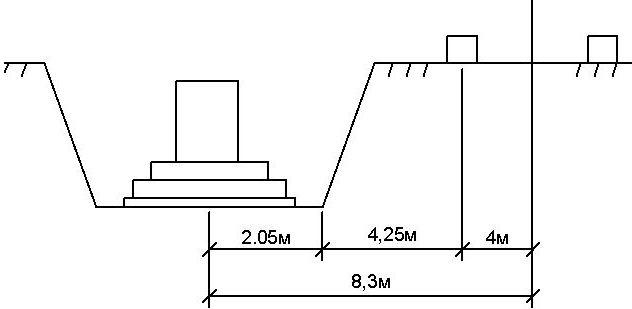
Determine the required hook reach:
![]() (2.2)
(2.2)
4.25 m - horizontal distance from the base of the excavation slope to the nearest machine support.
![]()
The MTT-16 crane meets these requirements.
We choose the MTT-16 crane. Boom radius 13m.
![]() (2.3)
(2.3)
Let's check the crane for maintenance from one parking lot of three foundations (B=6m):
Servicing three foundations from one station is not possible due to the crane's requirements not being met.
Let's check the crane for servicing from one parking lot of two foundations (B=3m):

Servicing two foundations from one station is not possible due to the crane's requirements not being met. 
Waterproofing device. Waterproofing is carried out from bitumen mastics and polymer-based solutions. The base must be pre-leveled, dust-free and primed. The compositions are applied evenly, in an equal layer 0.5-2 mm thick, without leaving gaps. On small areas
applied with brushes, manually.
Re-painting is performed after the previous layer has dried. To check whether the layer has dried or not, you need to apply a swab to the bitumen and there should be no traces left on it. Joints horizontal surface vertical waterproofing is first covered with mastic and then pasted over with strips roll material
- and after that the mastic is applied again. Roll strips should be 10-20 cm wide.
- The process of backfilling with sand or soil
- Consequences of errors
- Backfilling: sequence of work
- Compaction when backfilling
- Backfilling the base with rubble stone
Brief conclusions
When building a foundation, certain rules are followed that are designed to maintain the integrity of the structure and protect it. One of the stages of work is backfilling of soil, performed for the sinuses of the foundation. To compact the sinuses of the foundation, special machines are used: when filling with sand, a layer of up to 70 cm is made, sandy loam and loam (if the type of soil mostly consists of them) is filled with a layer of 60 cm, clay soils
covered with a layer of up to 50 cm. Held this work only after all The base is finished and has an excellent waterproofing layer. For backfilling, use only that which should not contain foreign particles, clay, branches, or construction debris. This will ensure that the foundation is reliably protected and its waterproofing is not damaged.
This kind of work takes quite a lot of time; even in clear and dry weather it will take several days to completely complete this process. It is recommended to carry out the filling itself only mechanized way, since it simply cannot be done manually as efficiently as required, and it will take too much time.
To lay soil in the sinuses, you need to prepare the following materials:
- soil or sand;
- cement milk;
- data on the geodesy of the site;
- laying excavator;
- a layer of waterproofing that will cover the foundation walls on the outside.
The process of backfilling with sand or soil
If the sinuses are filled with sand, then it is necessary to ensure the presence of a clean and sifted mixture, in which there will be no particles of clay and debris. The material is laid in layers, the thickness of each is up to 30 cm.
During backfilling, it is necessary to constantly ensure that foreign objects do not fall onto the working field, as this will negatively affect the quality of the structure.

Organic compounds are susceptible to rotting, so the resulting fill for the foundation sinuses will sag over time. This provokes a pressure difference under the foundation, the soil sags, the structure experiences severe loads, and begins to collapse.
Therefore, when filling with sand, attention must be paid to compaction; it is performed only mechanically. After compaction, the entire area is protected from above by a blind area of the selected type, and drainage is arranged.
Return to contents
Consequences of errors
Backfilling of the foundation should only be carried out in full compliance with the requirements and work rules, as otherwise unpleasant situations may arise. One of the main dangers is damage to the waterproofing layer. In the place where it is produced, the soil cannot be overloaded; it is recommended to arrange a strong and reliable blind area on top, which, in addition protective function will act as an excellent waterproofer, properly draining soil water from the base and walls of the house.
Backfilling is a responsible undertaking; sloppy work will not lead to anything good. Trying to get the job done faster, many people do not create a buffer zone. What is she? This is a special pillow that is located between the foundation layer and the base of the entire structure. Make a buffer from crushed stone or gravel; a layer of 10-20 cm is enough.
Return to contents
Backfilling: sequence of work

Waterproofing and thermal insulation of the blind area.
To complete the work of filling the foundation sinuses, you must strictly follow step by step instructions. The process is as follows:
- The first step is to check the condition of the soil on which this stage of work will be carried out. There should be no foreign materials, forgotten tools, concrete, or pieces of wood at the backfill site. This is very important for the quality of further work;
- Next, you need to check the moisture level of the soil at which the foundation sinuses will be filled. The humidity level should be normal, average, fully consistent with the standards. It is necessary to check if at the work site engineering Communication, pipes. If the pipes lie at the backfill site, then they should be at a depth of 30 cm from the bottom of the prepared pit. If they go higher, then it is necessary to add additional soil and level the base. The bedding will definitely have to be compacted and sprinkled with soft soil;
- backfilling is carried out with a bulldozer, since it is very difficult to do this manually and will take a lot of time. If compaction is not required, then the soil must be laid in such a way that a small bump remains on the surface. This will allow the soil area to settle correctly, and there will be no dangerous subsidence that could lead to structural movement. If a tamper was used when filling the foundation sinuses, then the density of the layer should be constantly checked so that it is uniform. Only a specialist can analyze the soil in the foundation sinuses.
Return to contents
Compaction when backfilling

After the work of filling the foundation sinuses has been completed, it is necessary to begin compacting. But before that, it’s worth arranging drainage, waterproofing layer. It is necessary to completely remove all garbage, residues building materials, complete the work on improving the entire underground part of the foundation, if there is such a need.
Tamping hand tools It is not recommended to do this, as it can be achieved required quality it won’t work, and the process itself will be labor-intensive and time-consuming.
- To compact the sinuses of the foundation, special machines are used:
- when filling with sand, a layer of up to 70 cm is made;
- sandy loams and loams (if the type of soil mostly consists of them) are covered with a layer of 60 cm;
clay soils are covered with a layer of up to 50 cm.
Return to contents
If backfilling will be carried out without the use of equipment, then the work must be done gradually; it is best to do layers no more than 30 cm at a time. It is recommended to start tamping from the walls of the house or foundation. Particular attention must be paid to those areas that pass near the pipes. The layer of soil or other bulk material for the foundation cavities should not be more than 20 cm. When performing work, the requirements and rules must not be neglected, since this process is complex, but very important, no mistakes are allowed here.

Backfilling the base with rubble stone Among the common materials used for foundation construction are: low-rise buildings
- , quite often ordinary rubble stone is used. It has numerous advantages, including high strength, resistance to frost and moisture. To ensure that the backfill is of proper quality, use:
- crushed stone of small and medium fraction;
- coarse purified sand;
special sand and gravel mixture. Backfilling of the foundation sinuses is carried out only in layers, the thickness of each should be 30 cm. Careful compaction by mechanical or manual method is required. Before you start working, you need to immediately prepare the mass, arrange special drainage channels


