Welding machines from scrap materials. Homemade mini welding at home Make a welding machine
From the article you will learn what they are. Making them with your own hands is quite simple if you have basic knowledge of electrical engineering and necessary tools. Both a ready-made transformer and a home-made one can be used as the basis for an automatic welding machine.
Of course, such designs consume a lot of power, therefore, there will be a strong voltage drop in the network. This may affect the functioning of household electrical appliances. It is for this reason that designs based on semiconductor elements are much more effective. To put it simply, these are devices.
The simplest welding machine
So, the first step is to consider the simplest designs that anyone can repeat. Of course, these are devices that are based on transformers. The design discussed below allows operation from 220 and 380 Volts. The maximum diameter of the electrode used in welding is 4 millimeters. Thickness of welded metal elements fluctuates in the range from 1 to 20 millimeters. You will now learn about this in full. Moreover, you can move from simple to complex.
Despite such excellent characteristics, the welding machine is manufactured from readily available materials. For assembly you will need a step-down transformer operating on three-phase voltage. Moreover, its power should be about 2 kilowatts. It is also worth noting that you will not need all the windings. Therefore, if one of them fails, there will be no problems with further design.
Transformer conversion
The bottom line is that you only need to make changes to the secondary winding. To make the task easier, the article below shows a diagram of the welding machine; connecting it to the network is also described.

So, you don’t need to touch the primary winding; it has all the characteristics necessary to operate from a 220 Volt alternating current network. There is no need to disassemble the core; it is enough to directly disassemble the secondary winding on it and wind a new one in its place.
The transformer you must select has several windings. Three primary, the same number of secondary. But there are also middle windings. There are also three of them. It is instead of the middle one that you need to wind the same wire that was used to make the primary one. Moreover, it is necessary to make taps from every thirtieth turn. Each winding should have about 300 turns in total. By properly winding the wire, you can increase the power of the welding machine.
A secondary winding is wound on both outer coils. Exact amount It is difficult to indicate turns, since the more there are, the better. The wire used has a cross-section of 6-8 square millimeters. A thin wire is wound along with it at the same time. As power cable you need to use multi-core in reliable insulation. This is exactly how they are made with their own hands.
If we analyze all the structures made using this technology, it turns out that the approximate amount of wire is about 25 meters. If there is no wire with a large cross-section, you can use a cable with an area of 3-4 square millimeters. But in this case it must be folded in half when winding.
Transformer connection
The design is of a simple welding machine. A semi-automatic machine can be made on its basis if one more winding is made to power the electric drive for supplying electrodes. Please note that the output of the transformer will be very high current. Therefore, all switching connectors must be made as durable as possible.

To make terminals to connect to the secondary winding terminals, you will need copper tubing. It should have a diameter of 10 millimeters and a length of 3-4 cm. It needs to be riveted at one end. The result should be a plate in which you need to make a hole. Its diameter should be about one centimeter. Wires are inserted from the other end. Regardless of whether the welding machine is DC or AC, the switching is made as rigid and reliable as possible.

It is advisable to clean them perfectly, if necessary, treat them with acid and neutralize it. To improve contact, the second edge of the tube should be slightly flattened with a hammer. It is best to attach the leads of the primary winding to a textolite board. Its thickness should be about three millimeters, more is possible. It is rigidly attached to the transformer. In addition, 10 holes need to be made in this board, each with a diameter of about 6 millimeters. Look at the diagram of the welding machine, how it is connected to the 220 and 380 Volt network.
They need to be installed with screws, nuts and washers. The terminals of all primary windings are connected to them. In the event that welding is required to operate from a 220-volt household network, the outer windings of the transformer are connected in parallel. The middle winding is connected in series with them. Welding will work ideally with a power supply of 380 Volts.
To connect the primary windings to the power supply network, you need to use a different circuit. Both outer windings are connected in series. Only after this the middle winding is switched on in series with them. The reason for this lies in the following: the middle winding is additional, with its help the voltage and current are reduced during secondary circuit. Thanks to this, welding machines made with their own hands using the above technology operate in normal mode.
Manufacturing of the electrode holder

Of course, an integral part of any welding machine is the electrode holder. There is no need to buy ready-made if you can make it from scrap materials. You need a three-quarter pipe, its total length should be about 25 centimeters. It is necessary to make small notches at both ends, approximately 1/2 of the diameter. The welding machine will work normally with such a holder. For plastic structural elements separate requirement- they should be located as far as possible from the transformer and holder.
They need to be done three to four centimeters from the edge. Then take a piece of steel wire, the diameter of which is 6 millimeters, weld it to the pipe opposite the larger recess. On the other side, you need to drill a hole, attach a wire to it that will connect to the secondary winding.
Network connection

It is worth noting that you need to connect the welding machine according to all the rules. Firstly, you need to use a switch, with which you can easily disconnect the device from the network. Please note that welding machines made by yourself should not be inferior in safety to analogues produced by industry. Secondly, the cross-section of the wires for connecting to the network must be at least one and a half square millimeters. The current consumption of the primary winding is a maximum of 25 amperes. In this case, the current can be changed in the range of 60..120 amperes. Please note that this design is relatively simple, so it is only suitable for domestic use.
Spot welding machine

A spot welding machine will also be useful. The designs of such devices are no less simple than the previous ones. True, the output current is very large. But it is possible to carry out contact welding of metals up to three millimeters thick. Most designs do not have output current adjustment. But you can do this if you wish. True, the whole homemade product becomes more complicated. There is no need to regulate the output current, since the welding process can be controlled visually. Of course, inverter welding machines will be much more efficient. But point ones can do things that any other design cannot do.
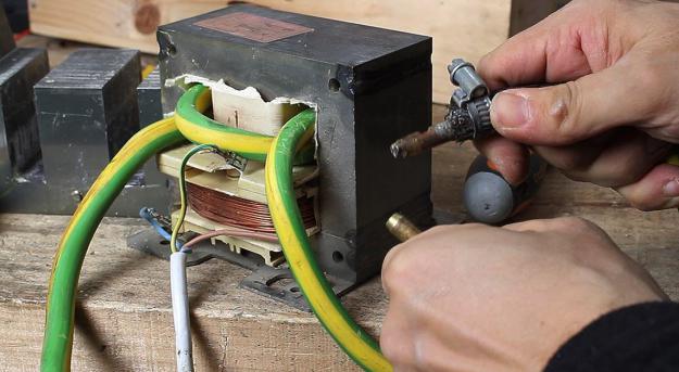
For manufacturing you will need a transformer with a power of about 1 kilowatt. The primary winding remains unchanged. Only the secondary one will need to be redone. And if you use a transformer from a household microwave, then you need to knock out the secondary winding and wind several turns of wire instead large section. If possible, it is better to use a copper busbar. The output should be about five volts, but this will be enough for full-fledged work devices.
Electrode holder design

Here it is slightly different from the one discussed above. For manufacturing you will need small duralumin blanks. Rods with a diameter of 3 centimeters are suitable. The bottom one must be motionless, completely isolated from contacts. As insulating material you can use washers made of textolite, as well as varnished fabric. Any, even the simplest spot welding machine needs a reliable electrode holder, so pay maximum attention to its design.
The electrodes are made of copper, their diameter is 10-12 millimeters. They are firmly fixed in the holder using rectangular brass inserts. The initial position of the electrode holder is that its halves are separated. Springs can be used to add elasticity. Ideal for old folding beds.
Resistance welding work

It is necessary to connect such welding to the electrical network using a circuit breaker. It must have a current rating of 20 amps. Please note that at the entrance (where your counter is located) the machine must be either the same in parameters or larger. To turn on the transformer, a simple magnetic starter is used. The operation of a contact-type welding machine is somewhat different from that discussed above. And you will now recognize these features.
To turn on the magnetic starter, you need to provide a special pedal, which you will press with your foot to generate current in the secondary circuit. Please note that resistance welding is turned on and off only if the electrodes are completely brought together. If you neglect this rule, a lot of sparks will appear, and as a result, this will lead to burning of the electrodes and their failure. Try to pay attention to the temperature of the welding machine as often as possible. Take short breaks from time to time. Do not allow the unit to overheat.
Inverter welding machine

It is the most modern, but more difficult to design. It also uses high-power semiconductor transistors. Perhaps these are the most expensive and scarce parts. First of all, the power supply is made. It is pulsed, so it is necessary to make a special transformer. And now in more detail about what such a welding machine consists of. See below for the characteristics of its components.
Of course, the transformer used in the inverter is much smaller in size than those discussed above. You will also need to make a throttle. So, you should get a ferrite core, a frame for making a transformer, copper busbars, special brackets to fix the two halves of the ferrite core, and electrical tape. The latter must be selected based on the data of its thermal resistance. Follow these tips when making inverter welders.
Transformer winding
The transformer is wound over the entire width of the frame. Only under this condition will it be able to withstand any voltage drops. For winding, either a copper busbar or wires collected in a bundle are used. Please note that aluminum wire cannot be used! It can't handle that much density electric current, which is available in the inverter. Such a welding machine for a summer house can help you out, and its weight is extremely light. The coils are wound as tightly as possible. The secondary winding is two wires with a thickness of about two millimeters, twisted together.
They should be isolated from each other as much as possible. If you have large supplies of old TVs, you can use them in the design. 5 pieces are required, and you need to make one common magnetic circuit out of them. For the device to work with maximum efficiency, you need to pay attention to every little detail. In particular, the thickness of the transformer output winding wire affects its uninterrupted operation.
Inverter design

To make a welding machine 200, it is necessary to pay maximum attention to all the details. In particular, power transistors must be mounted on a radiator. Moreover, the use of thermal paste is encouraged to transfer heat from the transistor to the heatsink. And it is recommended to change it from time to time, as it tends to dry out. In this case, heat transfer deteriorates, and there is a possibility that the semiconductors will fail. In addition, forced cooling needs to be done. Exhaust coolers are used for this purpose. Diodes used to rectify alternating current must be secured to aluminum plate. Its thickness should be 6 millimeters.
The connection of the terminals is carried out using not insulated wire. Its cross-section should be 4 millimeters. Please ensure that there is a maximum distance between the connection wires. They should not touch each other, no matter what impact the body of the welding machine experiences. The choke must be secured to the base of the welding machine using a metal plate.

Moreover, the latter must completely repeat the shape of the throttle itself. To reduce vibration, it is necessary to install a rubber seal between the body and the throttle. The power wires inside the device are routed in different directions. Otherwise, there is a possibility that a short circuit will occur. It is necessary to install the fan in such a way that it blows air across all radiators at the same time. Otherwise, if you cannot use one fan, you will have to install several.
But it is better to fully calculate in advance the installation location of all system elements. Please note that the secondary winding must be cooled as efficiently as possible. As you can see, not only radiators need effective airflow. On this basis, you can make an argon welding machine at no cost. But its design will require the use of other materials.
Conclusion
Now you know how to make several types of welding machines. If you have skills in designing radio-electronic equipment, then it is, of course, better to choose an inverter welding machine. You will spend time, but at the end you will get an excellent device that is not inferior even to expensive Japanese analogues. Moreover, its production will cost mere pennies.

But if there is a need to make a welding machine, as they say, a quick fix, then it will be easier to connect two transformers from microwave ovens with modified secondary windings. Subsequently, the entire unit can be improved by adding an electric drive to supply electrodes. You can also install a cylinder filled with carbon dioxide, in order to carry out metal welding in its environment.
It makes sense to make a welding machine yourself when it is necessary to carry out relatively small volumes welding work in domestic conditions. Knowing the basic principles of operation of the device, you can assemble it from easily accessible parts and materials.
First of all, it is worth determining what power welding current will be needed at work. Obviously, processing thin sheets of metal up to 2 mm requires much lower current intensity than for massive reinforcement. Depending on these characteristics of the material, the diameter of the electrode is selected. For parts to be welded with a thickness of up to 2 mm, an electrode with a diameter of 1.5 – 3 mm is suitable. Accordingly, for parts 3-5 mm - a 3-4 mm electrode, parts up to 10 mm - a 4-5 mm electrode, parts up to 24 mm - a 5-6 mm electrode and parts up to 60 mm - a 6-8 mm electrode.


, manufactured independently using carefully selected components, can fully replace an expensive ready-made device and reliably serve the owner for many years.
If you need to perform some simple welding work for domestic needs, it is not at all necessary to purchase an expensive factory unit. After all, if you know some subtleties, you can easily assemble a welding machine with your own hands, which will be discussed below.
 Welding machines: classification
Any welding machines can be electric or gas. It’s worth saying right away that homemade welding machines should not be gas. Since they include explosive gas cylinders, you should not keep such a unit at home. Therefore, in the context self-assembly designs we'll talk exclusively about electrical options
- . Such units are also divided into varieties: Generator units - equipped own generator current.- large weight and dimensions. This option is not suitable for home needs, and it will be difficult to assemble it yourself.
- Transformers - such installations, especially the semi-automatic type, are very common among those who make welding equipment on one's own. They are powered from a 220 or 380 V network.
- Inverters - such installations are easy to use and ideal for home use; the design is compact and lightweight, but electronic circuit quite complicated.
- Rectifiers - these devices are easy to assemble and use for their intended purpose. With their help, even a beginner can make high-quality welds.
To assemble an inverter at home, you will need a circuit that will allow you to comply with the necessary parameters. It is recommended to take parts from old Soviet devices:

The following parameters can be selected for the device:
- It must work with electrodes whose diameter does not exceed 5 mm.
- The maximum operating current is 250 A.
- Voltage source - household network at 220 V.
- The welding current adjustment varies from 30 to 220 A.
The tool includes the following components:
- power unit;
- rectifier;
- inverter
Begin from winding transformer and proceed in the following sequence:
- Take a ferrite core.
- Perform the first winding (100 turns using 0.3 mm PEV wire).
- The second winding is 15 turns, wire with a cross section of 1 mm).
- The third winding is 15 turns of 0.2 mm PEV wire.
- The fourth and fifth - respectively 20 turns of wires with a cross section of 0.35 mm.
- To cool the transformer, use a computer fan.
In order for transistor switches to operate continuously, voltage should be applied to them after the rectifier and capacitors. Assemble the rectifier block according to the diagram on the board, and secure all components of the device in the housing. Can be used old radio casing, or you can do it yourself.
Installed from the front of the case led indicator, which shows that the device is connected to the network. Here you can put additional switch, as well as a protective fuse. It can also be installed on the back wall and even in the case itself.
It all depends on its size and design features. Variable resistance is installed on the front part of the housing, with its help you can adjust operating current. When you have assembled all the electrical circuits, check the device with a special device or tester and you can test it.
 The assembly of the transformer version will be slightly different from the previous one. This unit operates on alternating current, but for welding with direct current you need to assemble a simple attachment for it.
To work you will need transformer iron for the core, as well as several tens of meters of thick wire or thick copper busbar. All this can be found at the metal collection point. The core is best made U-shaped, toroidal or round. Many also take the stator from an old electric motor.
The assembly instructions for the U-shaped core look like this:
- Take transformer iron with a cross-section from 30 to 55 cm2. If the figure is higher, the device will be too heavy. And if the cross section is less than 30, the device will not be able to work correctly.
- Take a copper winding wire with a cross-section of about 5 mm 2, equipped with heat-resistant fiberglass or cotton insulation. Insulation is important because during operation the winding can heat up to 100 degrees or more. The winding wire has a square cross-section or rectangular section. However, such an option is difficult to find. An ordinary one with a similar cross-section will do, but you will only need to remove the insulation from it, wrap it in fiberglass and thoroughly soak it with electrical varnish, and then dry it. The primary winding has 200 turns.
- The secondary winding will require about 50 turns. There is no need to cut the wire. Connect the primary winding to the network, and on the secondary wires find a place where the voltage is about 60 V. To find such a point, unwind or wind additional turns. The wire can be aluminum, but the cross-section must be 1.7 times larger than for the primary winding.
- Install the finished transformer into the housing.
- To bring out the secondary winding, copper terminals are required. Take a tube with a diameter of 10 mm and a length of about 4 cm. Rivet its end and drill a hole with a diameter of 10 mm, and insert the end of the wire, previously cleared of insulation, into the other end. Next, crimp it with light hammer blows. To strengthen the contact of the wire with the terminal tube, apply notches to it with a core. Screw homemade terminals to the body with nuts and bolts. It is best to use copper parts. When winding the secondary winding, it is advisable to make taps every 5-10 turns, they will allow you to change the voltage on the electrode in steps;
- To make an electrical holder, take a pipe with a diameter of about 20 mm and a length of about 20 cm. At the ends, about 4 cm from the end part, cut out recesses to half the diameter. Insert the electrode into the recess and press it with a spring based on a welded bush of steel wire with a diameter of 5 mm. Attach the same wire that was used for the secondary winding to the second terminal using a nut and screw. Place a rubber tube with a suitable inner diameter onto the holder.
It is best to connect the finished device to the network using wires with a cross-section of 1.5 cm2 or more, as well as a switch. The current in the primary winding usually does not exceed 25 A, and in the secondary winding it fluctuates between 6-120 A. When working with electrodes with a diameter of 3 mm every 10-15 make stops to allow the transformer to cool down. If the electrodes are thinner, this is not necessary. More frequent breaks are needed if you are working in cutting mode.
Do-it-yourself mini-welding
To assemble a miniature welding machine yourself, you will only need a few hours and the following materials:

Gently first disassemble the old battery and extract from it graphite rod. Sharpen the end with sandpaper and wipe with a dry cloth. Clean a piece of thick wire 4-5 cm from the end from the insulation and use pliers or side cutters to bend a loop. Insert a carbon electrode into it.
Remove the secondary winding from the transformer and replace it with wind thick wire for 12-16 turns. Now all this is inserted into a suitable housing - and the device is ready.
Its wires are connected to the terminals of the secondary winding, carbon the rod is inserted into the loop and crimps well. Connect the positive terminal to the electrode holder, and the negative terminal to the twist of the working parts. The holder handle can be adapted for an electrode.
You can use a soldering iron handle or something similar. Connect the device to a household network and perform joining parts using graphite. A flame should appear, and a spherical weld seam will form at the end of the parts.
For a home workshop, having a welding machine is very important. Such devices have different designs and modifications. Both beginners and experienced craftsmen often they prefer not factory-made, but home-made devices that can be modified in their own way.
Figure 1. Diagram of a bridge rectifier for a welding machine.
Welding machines come in direct and alternating current.
S.A. direct current are used for low current welding of thin sheet metal (roofing steel, automotive, etc.). The DC welding arc is more stable; direct and reverse polarity welding is possible. You can weld on direct current using electrode wire without coating and electrodes designed for welding on both direct current and alternating current. To make the arc burning stable at low currents, it is desirable to have an increased open-circuit voltage Uxx of the welding winding (up to 70 - 75 V). To rectify alternating current, the simplest “bridge” rectifiers on powerful diodes with cooling radiators are used (Fig. 1).
To smooth out voltage ripples, one of the outputs of S.A. And they are connected to the electrode holder through inductor L1, which is a coil of 10 - 15 turns of a copper bus with a cross section of S = 35 mm 2, wound on any core, for example, from. To rectify and smoothly regulate the welding current, more complex circuits are used using powerful controlled thyristors. One of possible schemes on thyristors of type T161 (T160) is given in the article by A. Chernov “And it will charge and weld” (Model Designer, 1994, No. 9). The advantages of DC regulators are their versatility. The range of their voltage changes is 0.1-0.9 Uxx, which allows them to be used not only for smooth adjustment of welding current, but also for charging batteries, powering electric heating elements and other purposes.

Figure 2. Diagram of the falling external characteristic of the welding machine.
Rice. 1. Bridge rectifier for welding machine. Connection shown S.A. for welding thin sheet metal with “reverse” polarity - “+” on the electrode, “-” on the part being welded U2: - output alternating voltage of the welding machine
AC welding machines are used when welding with electrodes whose diameter is more than 1.6 - 2 mm, and the thickness of the welded products is more than 1.5 mm. In this case, the welding current is significant (tens of amperes) and the arc burns quite steadily. Electrodes designed for welding with alternating current only are used. For normal operation of the welding machine it is necessary:
- Provide output voltage for reliable arc ignition. For amateur S.A. Uxx = 60 - 65v. A higher open circuit output voltage is not recommended, which is mainly due to ensuring operational safety (Uxxindustrial welding machines - up to 70 - 75 V).
- Provide the welding voltage Usv necessary for stable arc burning. Depending on the diameter of the electrode - Usv = 18 - 24 V.
- Provide rated welding current Iw = (30 - 40) de, where Iw is the value of the welding current, A; 30 - 40 - coefficient depending on the type and diameter of the electrode; dе - electrode diameter, mm.
- Limit the short circuit current Isk, the value of which should not exceed the rated welding current by more than 30 - 35%.
Stable arc burning is possible if the welding machine has a falling external characteristic, which determines the relationship between the current strength and voltage in the welding circuit (Fig. 2).
S.A. shows that for rough (stepwise) overlap of the range of welding currents, switching of both primary and secondary windings is necessary (which is structurally more difficult due to the large current flowing in it). In addition, to smoothly change the welding current within the selected range, mechanical devices movement of the windings. When the welding winding is removed relative to the network winding, the magnetic dissipation fluxes increase, which leads to a decrease in the welding current.

Figure 3. Diagram of a rod-type magnetic circuit.
When designing an amateur SA, one should not strive to completely cover the range of welding currents. It is advisable at the first stage to assemble a welding machine for working with electrodes with a diameter of 2 - 4 mm, and at the second stage, if it is necessary to work at low welding currents, supplement it with a separate rectifier device with smooth control of the welding current. Amateur welding machines must satisfy a number of requirements, the main ones being the following: relative compactness and low weight; sufficient operating time (at least 5 - 7 electrodes dе = 3 - 4 mm) from a 220V network.
The weight and dimensions of the device can be reduced by reducing its power, and the operating time can be increased by using steel with high magnetic permeability and heat-resistant insulation of the winding wires. These requirements are easy to meet if you know the basics of welding machine design and adhere to the proposed technology for their manufacture.
Rice. 2. Falling external characteristic welding machine: 1 - family of characteristics for different welding ranges; Isv2, Isvz, Isv4 - ranges of welding currents for electrodes with a diameter of 2, 3 and 4 mm, respectively; Uxx - CA open circuit voltage. Is - current short circuit; Ucv - welding voltage range (18 - 24 V).
Rice. 3. Rod-type magnetic core: a - L-shaped plates; b - U-shaped plates; c - plates made of transformer steel strips; S =axb- area cross section core (core), cm 2 s, d- window dimensions, cm.
So, choosing the type of core. For the manufacture of welding machines, rod-type magnetic cores are mainly used, since their design is more technologically advanced. The core is made from electrical steel plates of any configuration with a thickness of 0.35-0.55 mm, tightened with pins insulated from the core (Fig. 3). When selecting a core, it is necessary to take into account the dimensions of the “window” to fit the windings of the welding machine, and the cross-sectional area of the core (core) S =axb, cm 2. As practice shows, you should not choose the minimum values of S = 25 - 35 cm, since the welding machine will not have the required power reserve and it will be difficult to obtain high-quality welding. Yes, and overheating of the welding machine after short work is also inevitable.

Figure 4. Diagram of a toroidal magnetic circuit.
The cross section of the core should be S = 45 - 55 cm 2. The welding machine will be somewhat heavier, but it will not let you down! Amateur welding machines on toroidal-type cores, which have higher electrical characteristics, are about 4 to 5 times higher than those of a rod type, and electrical losses are low, are becoming increasingly widespread. The labor costs for their manufacture are more significant and are associated primarily with the placement of the windings on the torus and the complexity of the winding itself.
However, when the right approach they give good results. The cores are made from transformer strip iron, rolled into a torus-shaped roll. An example is a core from a 9 A “Latr” autotransformer. To increase the internal diameter of the torus (“window”) with inside unwind part of the steel tape and wrap it around the outside of the core. But, as practice shows, Latra alone is not enough to produce high-quality SA. (small section S). Even after working with 1 - 2 electrodes with a diameter of 3 mm, it overheats. It is possible to use two similar cores according to the scheme described in B. Sokolov’s article “Welding Baby” (Sam, 1993, No. 1), or to produce one core by rewinding two (Fig. 4).
Rice. 4. Toroidal magnetic core: 1.2 - autotransformer core before and after rewinding; 3 design S.A. based on two toroidal cores; W1 1 W1 2 - network windings connected in parallel; W 2 - welding winding; S = axb - cross-sectional area of the core, cm 2, s, d - internal and external diameters of the torus, cm; 4 - electrical diagram S.A. based on two joined toroidal cores.
Amateur SAs made on the basis of stators of high-power asynchronous three-phase electric motors (more than 10 kW) deserve special attention. The choice of core is determined by the cross-sectional area of the stator S. Stamped stator plates do not fully correspond to the parameters of electrical transformer steel, therefore it is not advisable to reduce the cross-section S to less than 40 - 45 cm.

Figure 5. Scheme of fastening the terminals of the CA windings.
The stator is freed from the housing, the stator windings are removed from the internal slots, the groove bridges are cut off with a chisel, the inner surface is protected with a file or an abrasive wheel, the sharp edges of the core are rounded and wrapped tightly, covering it with cotton insulating tape. The core is ready for winding windings.
Selection of windings. For primary (network) windings, it is better to use a special copper winding wire in cold steel. (fiberglass) insulation. Wires in rubber or rubber-fabric insulation also have satisfactory heat resistance. Not suitable for use with elevated temperature(and this is already included in the design of amateur SA) wires in polyvinyl chloride (PVC) insulation due to its possible melting, leakage from the windings and their short circuit. Therefore, the polyvinyl chloride insulation from the wires must either be removed and the wires wrapped along the entire length of the cotton wool. with insulating tape, or do not remove it, but wrap the wire over the insulation. Another proven winding method is also possible. But more on that below.
When selecting the cross-section of the winding wires, taking into account the specifics of the work of S.A. (periodic) we allow a current density of 5 A/mm 2. With a welding current of 130 - 160 A (electrode dе = 4 mm), the power of the secondary winding will be P 2 = Isw x 160x24 = 3.5 - 4 kW, the power of the primary winding, taking into account losses, will be about 5 - 5.5 kW, and therefore the maximum current of the primary winding can reach 25 A. Consequently, the cross-section of the wire of the primary winding S 1 must be at least 5 - 6 mm. In practice, it is advisable to use a wire with a cross section of 6 - 7 mm 2. Either it is a rectangular busbar or a copper winding wire with a diameter (without insulation) of 2.6 - 3 mm. (Calculation using the well-known formula S = piR 2, where S is the area of the circle, mm 2 pi = 3.1428; R is the radius of the circle, mm.) If the cross-section of one wire is insufficient, winding in two is possible. When using aluminum wire its cross section must be increased by 1.6 - 1.7 times. Is it possible to reduce the cross-section of the network winding wire? Yes, you can. But at the same time S.A. will lose the required power reserve, will heat up faster, and the recommended core cross-section S = 45 - 55 cm in this case will be unreasonably large. The number of turns of the primary winding W 1 is determined from the following relationship: W 1 = [(30 - 50):S] x U 1 where 30-50 is a constant coefficient; S - core cross-section, cm 2, W 1 = 240 turns with bends from 165, 190 and 215 turns, i.e. every 25 turns.

Figure 6. Diagram of methods for winding CA windings on a rod-type core.
A larger number of network winding taps, as practice shows, is impractical. And that's why. By reducing the number of turns of the primary winding, both the power SA and Uxx increase, which leads to an increase in arc voltage and a deterioration in welding quality. Consequently, it is impossible to cover the range of welding currents without deteriorating the quality of welding by simply changing the number of turns of the primary winding. To do this, it is necessary to provide for switching the turns of the secondary (welding) winding W 2.
The secondary winding W 2 must contain 65 - 70 turns of an insulated copper busbar with a cross-section of at least 25 mm ( better cross section 35 mm). Suitable and flexible stranded wire(for example, welding) and three-phase power multi-core cable. The main thing is the section power winding should not be less than required, and the insulation should be heat-resistant and reliable. If the wire cross-section is insufficient, winding in two or even three wires is possible. When using aluminum wire, its cross-section must be increased by 1.6 - 1.7 times.
Rice. 5. Fastening the terminals of the CA windings: 1 - CA housing; 2 - washers; 3 - terminal bolt; 4 - nut; 5 - copper tip with wire.
The difficulty of purchasing switches for high currents, and practice shows that it is easiest to insert the welding winding leads through copper lugs under terminal bolts with a diameter of 8 - 10 mm (Fig. 5). Copper lugs are made from copper tubes of suitable diameter 25 - 30 mm long and attached to the wires by crimping and preferably soldering. Let us especially focus on the order of winding the windings. General rules:
- Winding should be done along an insulated core and always in the same direction (for example, clockwise).
- Each layer of the winding is insulated with a layer of cotton wool. insulation (fiberglass, electrical cardboard, tracing paper), preferably impregnated with bakelite varnish.
- The winding terminals are tinned, marked, and secured with cotton wool. braid, additionally put cotton on the terminals of the network winding. cambric.
- In case of doubt about the quality of insulation, winding can be carried out using a cotton cord, as if in two wires (the author used cotton thread for fishing). After winding one layer, winding with cotton. the thread is fixed with glue, varnish, etc. and after drying, wind the next row.

Figure 7. Diagram of methods for winding CA windings on a toroidal core.
Let's consider the order of arrangement of windings on a rod-type magnetic core. The network winding can be positioned in two main ways. The first method allows you to obtain a more “hard” welding mode. The network winding in this case consists of two identical windings W 1 W 2, located on different sides of the core, connected in series and having the same wire cross-section. To adjust the output current, taps are made on each of the windings, which are closed in pairs (Fig. 6a, c).
The second method involves winding the primary (network) winding on one side of the core (Fig. 6 c, d). In this case, the SA has a steeply falling characteristic, welds “softly”, the arc length has less influence on the value of the welding current, and therefore on the quality of welding. After winding the primary winding of the CA, it is necessary to check for the presence of short-circuited turns and the correctness of the selected number of turns. The welding transformer is connected to the network through a fuse (4 - 6A) and preferably an AC ammeter. If the fuse burns out or gets very hot, it is a clear sign short-circuited turn. Consequently, the primary winding will have to be rewound, paying special attention to the quality of the insulation.
Rice. 6. Methods for winding CA windings on a rod-type core: a - network winding on both sides of the core; b - the corresponding secondary (welding) winding, connected back-to-back; c - network winding on one side of the core; g - the corresponding secondary winding, connected in series.
If the welding machine makes a loud noise and the current consumption exceeds 2 - 3 A, then this means that the number of primary windings is underestimated and it is necessary to wind up a certain number of turns. A working CA consumes no-load current of no more than 1 - 1.5 A, does not heat up and does not buzz much. The secondary winding CA is always wound on both sides of the core. For the first winding method, the secondary winding also consists of two identical halves, connected to increase the stability of arc burning (Fig. 6) in counter-parallel, and the wire cross-section can be taken slightly smaller - 15 - 20 mm 2.

Figure 8. Connection diagram for measuring instruments.
For the second winding method, the main welding winding W 2 1 is wound on the side of the core free from windings and amounts to 60 - 65% of total number turns of the secondary winding. It serves mainly to ignite the arc, and during welding, due to a sharp increase in the magnetic dissipation flux, the voltage on it drops by 80 - 90%. An additional welding winding W 2 2 is wound on top of the primary one. Being a power source, it maintains the welding voltage and, consequently, the welding current within the required limits. The voltage across it drops in welding mode by 20 - 25% relative to the no-load voltage. After manufacturing the SA, it is necessary to set it up and check the quality of welding with electrodes of different diameters. The setup process is as follows. To measure welding current and voltage, you need to purchase two electrical measuring instruments - an AC ammeter for 180-200 A and an AC voltmeter for 70-80 V.
Rice. 7. Methods for winding CA windings on a toroidal core: 1.2 - uniform and sectional winding of windings, respectively: a - network b - power.
Their connection diagram is shown in Fig. 8. When welding with different electrodes, take the values of the welding current - Iw and welding voltage Uw, which must be within the required limits. If the welding current is small, which happens most often (the electrode sticks, the arc is unstable), then in this case, either by switching the primary and secondary windings, the required values are set, or the number of turns of the secondary winding is redistributed (without increasing them) towards increasing the number of turns wound on top network winding. After welding, you can make a break or saw the edges of the welded products, and the quality of the weld will immediately become clear: the depth of penetration and the thickness of the deposited layer of metal. It is useful to create a table based on the measurement results.
![]()
Figure 9. Diagram of welding voltage and current meters and design of a current transformer.
Based on the data in the table, select the optimal welding modes for the electrodes various diameters, remembering that when welding with electrodes, for example, with a diameter of 3 mm, electrodes with a diameter of 2 mm can be cut, because The cutting current is 30-25% higher than the welding current. The difficulty of purchasing the measuring instruments recommended above forced the author to resort to making a measuring circuit (Fig. 9) based on the most common 1-10 mA DC milliammeter. It consists of voltage and current meters assembled using a bridge circuit.
Rice. 9. Schematic diagram welding voltage and current meters and current transformer design.
The voltage meter is connected to the output (welding) winding SA. The setting is carried out using any tester that controls the welding output voltage. Using a variable resistance R.3, the arrow of the device is set to the final scale division at the maximum value of Uxx. The voltage meter scale is quite linear. For greater accuracy, you can remove two or three control points and calibrate measuring device for measuring voltages.
Setting up a current meter is more difficult because it is connected to a homemade current transformer. The latter is a toroidal core with two windings. The dimensions of the core (external diameter 35-40 mm) are not of fundamental importance, the main thing is that the windings fit. Core material - transformer steel, permalloy or ferrite. The secondary winding consists of 600 - 700 turns of insulated copper wire of the PEL, PEV brand, preferably PELSHO, with a diameter of 0.2 - 0.25 mm and is connected to a current meter. The primary winding is a power wire running inside the ring and connected to the terminal bolt (Fig. 9). Setting up the current meter is as follows. To the power (welding) winding S.A. connect a calibrated resistance from thick nichrome wire for 1 - 2 seconds (it gets very hot) and measure the voltage at the SA output. The current flowing in the welding winding is determined. For example, when connecting Rн = 0.2 ohm Uout = 30V.

Mark a point on the instrument scale. Three to four measurements with different RH are enough to calibrate the current meter. After calibration, the instruments are installed on the CA body, using generally accepted recommendations. When welding in different conditions(strong or low-current network, long or short supply cable, its cross-section, etc.) by switching the windings, the SA is adjusted. to the optimal welding mode, and then the switch can be set to the neutral position. A few words about resistance spot welding. Towards the design of S.A. This type has a number of specific requirements:
- The power delivered at the time of welding should be maximum, but not more than 5-5.5 kW. In this case, the current consumed from the network will not exceed 25 A.
- The welding mode must be “hard”, and therefore, the winding of the windings S.A. should be carried out according to the first option.
- The currents flowing in the welding winding reach values of 1500-2000 A and higher. Therefore, the welding voltage should be no more than 2-2.5V, and the no-load voltage should be 6-10V.
- The cross-section of the primary winding wires is at least 6-7 mm, and the cross-section of the secondary winding is at least 200 mm. This cross-section of wires is achieved by winding 4-6 windings and then connecting them in parallel.
- It is not advisable to make additional taps from the primary and secondary windings.
- The number of turns of the primary winding can be taken as the minimum calculated due to the short duration of the operation of the SA.
- It is not recommended to take a cross-section of the core (core) less than 45-50 cm.
- Welding tips and underwater cables to them must be copper and pass appropriate currents (tip diameter 12-14 mm).
![]()
A special class of amateur S.A. represent devices manufactured on the basis of industrial lighting and other transformers (2-3 phase) with an output voltage of 36V and a power of at least 2.5-3 kW. But before undertaking the alteration, it is necessary to measure the cross-section of the core, which should be at least 25 cm, and the diameters of the primary and secondary windings.
It will immediately become clear to you what you can expect from remaking this transformer.
And finally, some technological tips.
The welding machine must be connected to the network using a wire with a cross-section of 6-7 mm through an automatic machine with a current of 25-50 A, for example AP-50. The diameter of the electrode, depending on the thickness of the metal being welded, can be selected based on the following relationship: da= (1-1.5)L, where L is the thickness of the metal being welded, mm.
![]()
The arc length is selected depending on the diameter of the electrode and is on average 0.5-1.1 d3. It is recommended to weld with a short arc of 2-3 mm, the voltage of which is 18-24 V. Increasing the length of the arc leads to a violation of the stability of its combustion, increased losses due to waste and spatter, and a decrease in the depth of penetration of the base metal. The longer the arc, the higher the welding voltage. The welding speed is selected by the welder depending on the grade and thickness of the metal.
When welding with straight polarity, the plus (anode) is connected to the part and the minus (cathode) to the electrode. If it is necessary for less heat to be generated on the parts, for example, when welding thin-sheet structures, reverse polarity welding is used (Fig. 1). In this case, the minus (cathode) is connected to the part being welded, and the plus (anode) is connected to the electrode. This not only ensures less heating of the part being welded, but also accelerates the process of melting the electrode metal due to the higher temperature of the anode zone and greater heat input. Welding wires are connected to the SA through copper lugs under the terminal bolts on the outside of the welding machine body. Bad contact connections
Welding work should be carried out in a special mask with protective glass grade C5 (for currents up to 150-160 A) and gloves. Perform all switching of the SA only after disconnecting the welding machine from the network.
Do-it-yourself welding machines for the home are most often created by craftsmen from scrap materials.
If you do not have the opportunity or desire to buy a welding machine, then you can assemble it yourself using ready-made elements.
However, to speed up the assembly process, ready-made components and parts can be used. A holder for electrodes can also be made on our own from those available in the arsenal home handyman materials.
The simplest welding machine

In a home craftsman's household, you may find a step-down transformer S-B22, IV-10, IV-8, the power of which is 1-2 kW. It reduces the voltage from 220 V to 36 V and serves to power power tools.
Welding machines based on such transformers can be assembled even with a failed winding.
The welding machine is manufactured as follows:
![]()
The secondary winding must be removed from the transformer.
- secondary windings are removed from the coils without damaging the primary ones;
- the middle primary coil is rewound with the same wire, creating taps with a total number of 8-10 pieces after 30 turns. (for convenience, it is better to number each of them as they are created);
- the two outer coils are filled with a multi-core cable (three 6-8 mm wires with a thin phase, 12-13 m are consumed for each coil);
- a copper pipe with a diameter of 10-12 mm is used for the terminal for the VO cable (one side crimps the wires, the other is flattened, drilled for fasteners with a diameter of 10 mm);
- on the top panel of the transformer, the M6 fasteners are replaced with a more powerful one (M10), and the VO terminals are attached to them;
- A board with 10 holes for software is made from PCB, and an M6 fastener is inserted into each hole.
Welding machines of this design are powered by a 380/220 V network. In the first case, the outer coils are connected in series, then the middle coils. In the second option, the outer windings are connected in parallel, the middle one is connected in series to the same circuit. The VO taps are placed in the terminals of the textolite plate 1 - 10. The current is regulated by terminals 1 - 10.
It is not recommended to carry out large volumes of work with this SA (maximum 15 “troika” electrodes).
To cut metal, the second end of the cable leading to the holder is connected to the cutting terminal (on the side of the middle PO coil). The characteristics of the VO current correspond to 60-120 A, in the software the current is always 25 A. When working with “two” electrodes, the transformer does not heat up above +70˚C, so the operating time is not limited. Welding/cutting modes are switched when the switch is turned off.
Return to contents
Machine for welding from car batteries

In order to invent a diesel generator for a welding machine, it is necessary to connect a pair of batteries in a certain sequence.
The welding machine seriously loads the household electrical network, providing a voltage surge of 30 V at a load of 3.5 kW. Instead of purchasing a welding diesel generator, craftsmen created an original device circuit, the basis of which is 3-4 series-connected batteries from passenger car. The capacity of each of them must be at least 55-190 A/h; reliable clamps must be used to combine them into a common circuit.
This scheme is indispensable in field conditions, since even used batteries delivered to the site by a passenger vehicle will help out. It is necessary to take into account the strong heating of battery cases after several hours of operation, check the level and density of the electrolyte daily with constant use. In hot weather, water evaporates rapidly from the electrolyte, so control devices (hydrometer), distilled water, and acid should be kept at hand.
Welding machines of this type simply need to be charged at night by connecting the appropriate device to a common circuit so that all batteries are charged at once. When welding with electrodes with a diameter of 3 mm, the operating current is no more than 90-120 A, which does not exceed half the power. The electrolyte does not boil due to its high heat capacity. The output voltage depends entirely on the number of batteries connected to the circuit and is 42-54 V.
Return to contents
Homemade toroidal welding machine

U-shaped and W-shaped transformers are significantly inferior to toroids in terms of weight and size. A toroidal welding machine is one and a half times lighter than its W-shaped counterpart, but the main difficulty in self-production lies in the lack of necessary iron. Craftsmen share recommendations for making a transformer from an industrial CA that has spent its required life. A similar replacement would be the TCA 310 or TS 270 transformer. Its U-shaped plates are “halved” with a chisel and adjusted on an anvil.
Welding machines of this type are assembled from 45 x 9 cm plates:
- a plate riveted hoop with a diameter of 26 cm is filled with plates end to end (the work is done by two people, a partner fixes the core being assembled, preventing the plates from straightening);
- when the internal diameter of the structure reaches 12 cm, the set stops;
- Details are cut out of electrical cardboard: a strip 9 cm wide, rings with an internal diameter of 11 cm, an external diameter of 27 cm;
- the rings are applied to the sides of the structure assembled at the first stage and wrapped with fabric tape;
- winding I is laid on electrical tape - 170 turns (for 220 V) of wire with a diameter of 2 mm, grade PEV-2;
- winding II is laid on top of it - 30 turns of wire with a diameter of 15-20 mm, grade PEV-3;
- winding III - 30 turns with MGTF 0.35 wire;
- insulation from each other with tape, the software is checked for the XX current: if it is less than 1-2 A, several turns are unwound; if the XX current is greater than 2 A, two turns are added.
This welding machine has an original control circuit in the form of a phase regulator. The voltage removed from winding III is rectified by a diode bridge. The capacitor is charged through resistors up to 6 V, then a breakdown occurs through a dinistor assembled from a thyristor and a zener diode. The diode with the thyristor opens. The last resistor in the circuit limits the current; when the alternating current wave is negative, the response thyristor and diode open. Welding machines of this design are tuned with a resistor.

To create a welding machine, resistors with a power of 10 W or more are required.
The scheme uses:
- diodes for a current of 160-250 A, mounted on radiators with an area of 100 cm2;
- capacitor K50-6;
- resistors with a power of 10 W;
- thyristors KU202 or KU201.
The welding machine confidently welds with electrodes with a diameter of 4 mm and cuts metal. You can make a holder for it yourself from an equal angle corner 10 cm long (shelves 2 cm each). A hole with a diameter of 4.1 mm is drilled 1 cm from the edge of the corner in the very corner, through which the burnt electrode can be pushed out with a new electrode. The lower part of the shelves will be narrowed according to the welder's hand. A wire is welded into the inner corner, bent vertically upward from it. A piece of rubber hose is placed on the structure from below. During operation, the electrode is inserted between the edges of the angle and pressed against them with a piece of welded wire.


