Is it necessary to do grounding in a wooden house? Proper grounding in a private home. Ground loop design
Compliance with electrical safety rules protects the health of residents and keeps household appliances in good working order in the event of an emergency in the power supply system.
Now there are a lot of articles and videos about how you can do grounding in a private house with your own hands. The Internet allows people to express their opinions, which are often quite erroneous.
In this article I show 2 options for schemes different designs, based on scientific recommendations with links to regulatory documents.
What electrical characteristics ensure safe operation of the ground loop?
The protective function of the circuit is based on the phenomenon that fault current flows along the path of least resistance.
Due to damage to the insulation, a phase potential may appear on the body of any household appliance. IN old system grounding TN-C, it will flow through the body of the person who touches it.
The severity of an electrical injury depends on many factors, but can also lead to fatal consequences.
In the TN-S power supply circuit, an artificially created PE conductor through the grounding loop removes dangerous potential and protects a person from electric shock.

For optimal performance diagrams must be taken into account:
- resistance to spreading;
- touch and step tension;
- soil condition based on its resistivity;
- electrical characteristics selected materials and their resistance to aggressive soil environments;
- circuit design, which must be calculated according to standards and verified by electrical measurements with high-precision instruments.
Resistance of the grounding device in electrical installations up to 1000 V: what components does it consist of?
Any grounding loop consists of vertical or horizontal grounding conductors (electrodes) located in the ground. An emergency current flows through the contact they create.

Vertical electrodes are buried in the soil, spaced at a certain distance, and united by a horizontal ground electrode connected to the main busbar of the building.
For a private house, one vertical ground electrode is rarely used due to the resistance to current flow.
Let us assume that there is a structure with one vertical electrode connected to it, located in the soil. The main bus is equipped with a metal short circuit. the conductor is neglected for simplicity.

On the border certain area, called the spreading zone, the voltage decreases to almost zero from its maximum value. In this way we obtained points of zero potential located with opposite sides electrodes on which U=0.
The resistance of the grounding device Rз is resistance of a piece of land between points of zero potential. It is calculated using the formula Rз=Uф/Iкз.
Its value is very little affected by the resistance of the metal parts of the grounding conductors with the busbar and the contacts of the electrodes with the ground - they are very small. The issue of reducing it is solved by changing the contour design and soil characteristics.
This indicator can be improved by installing an additional electrode. However, it must be mounted in a certain way.
If two electrodes are placed side by side, the area of the spreading zone remains virtually unchanged. The short circuit current flows into the same area of soil. Therefore, grounding conductors must be spaced over a greater distance.
In this case, the short-circuit current will flow from each electrode, dividing into two flows, and a space will form between them where they influence each other. This is called the shielding zone. To assess its characteristics, correction factors have been introduced.

The second method of improving the resistance of a grounding device is based on increasing the length of the vertical electrode and burying it in the ground to 30 meters. The technology of this method is given at the end of the article.
Several vertical electrodes are welded in the soil to a metal strip (horizontal ground electrode). It also affects the flow of emergency current and is assessed by an individual coefficient.
Its value depends on the number of electrodes in the circuit and the ratio of the distance between them to their length. The data is summarized in a table.

Thus, the electrical characteristics of the created circuit strongly depend on the configuration and location of vertical and horizontal ground electrodes and their penetration into the ground.
The owner of a private house needs to evaluate the resistance of the grounding device in electrical installations up to 1000 V and make a preliminary calculation on paper before starting to assemble the structure. To do this, you need to understand from which processes the parameters specified in the project are taken.
Touch and step voltage: what is it and how does it affect ground loop design
Describes clause PUE 1.7.24. Its value is included in the formulas for calculating the ground loop resistance.
Let's imagine that a phase potential U appears on the body of some equipment and a person with body resistance R touches it.
Current It, which is determined by Ohm’s law, will begin to flow through it. The magnitude of the applied voltage depends on the place where the contact is created, the distance from the maximum value of U, and is designated by the term touch (Upr).

Since human safety depends on Upr, strict standards have been introduced for it. When creating an electrical project for a facility, it is subject to strict restrictions that affect safety. They are taken into account in the permissible resistance parameters of the grounding device.
Another number of factors that influence the calculation of the circuit is taking into account those processes that occur directly on the ground during the flow of emergency current, distributed within the area where a person may accidentally find himself. They are taken into account by the step voltage.
At the epicenter of the discharge, applied maximum voltage, and its value gradually decreases with increasing distance to zero. When a person moves in this zone, a potential difference will arise between his legs.
It increases as you approach the discharge site, and under certain conditions can lead to electrical injury: the closer to the center, the more dangerous.

The step voltage term Ush is included in clause PUE 1.7.25. It is strictly standardized by the formulas for calculating the design of grounding devices.
Industrial facilities usually use expensive special protections that quickly turn off emergency modes, when the step tension has a very short time to express itself.
There are no such devices in a private home. Therefore, increased demands are placed on the quality of the circuit. The owner needs to consider its location and the route of the horizontal ground electrode.
The stress of touch and step is sought to be kept as minimal as possible to ensure increased human safety. They are taken into account by the PUE standards.
What standards for resistance to spreading are included in the PUE and why?
To create a reliable circuit for a private home, you should understand that it does not work on its own, but as part of the entire grounding system of an electrical installation, starting from an industrial transformer substation.
Safety depends on the type of neutral point of the transformer transformer and the speed of emergency response.
At industrial facilities that require prompt shutdown of emergencies, an effectively grounded neutral is created, which allows short-circuit currents to be quickly shutdown in case of single-phase ground faults. To do this, its resistance, taking into account the influence of all natural and artificial grounding conductors, should not exceed 0.5 Ohm. (Clause 1.7.90.)
A household electrical network of 380/220 volts is usually created with a solidly grounded neutral. Its safety in some part can be improved by an isolation transformer.

A network with an isolated neutral is created behind it. But we are now considering another issue.
Transformer substation connected via the usual scheme with a grounded neutral, must operate in the mode provided for in clause PUE 1.7.101.

This means that when powering a private house with a voltage of 380/220 volts, the total resistance of the entire chain of grounding devices must fall within the standard of less than 4 ohms. This value is influenced by all repeated grounding of overhead lines and natural grounding.
The latter include reinforced concrete foundations of buildings and other metal structures buried in the ground. Their task is to provide long-term electrical contact with the ground.
Repeated line grounding conductors are distributed among overhead line supports to ensure a sufficient magnitude of single-phase fault current, which must be felt current protection. They are placed at the entrance to the building.
All these groundings together should provide a resistance value of 0.4 Ohm at the transformer substation.
When overhead lines and transformer transformers are put into operation, then any grounding installed on them is in operation. Measuring its resistance separately is impossible and very dangerous: it is part of the electrical circuit.
Now let's continue our consideration of paragraph PUE 1.7.107. for the grounding device of a private house. Other standards are already given here.

For the ground electrode we are creating, a value of 30 Ohms has been introduced. The ground loop can be disconnected from the main shield and its resistance can be measured. We understand that in operation it participates with all the repeated and natural grounding conductors of the circuit and provides 4 Ohms for the transformer at the transformer substation.
But it's not that simple. We will need to fulfill one more safety condition: the resistance of the nearest repeated grounding electrode must be 10 Ohms. This is stated in paragraph PUE 1.7.103.

However, to provide these 10 and 30 Ohms in simple ways not always possible due to the physical condition of the soil.
Types of soils and their resistivity: what requires mandatory consideration
Our circuit will be driven into the ground, which serves as a conductor of electric current. Its conductivity depends on many factors and is normalized by the resistivity value.
For example, rocky ground has very poor characteristics. Working on it is a bad idea. The normalized parameters and possible limits of their deviation are placed in the table.

This information is presented as indicative for making an approximate calculation. When creating a contour design, it is advisable to clarify them on a specific area.
The moister the soil and the more different salts it contains, the better it is. resistivity. However saline solutions- This is an aggressive environment that causes corrosion of metals.
It is the constant fluctuations in moisture, depending on the time of year and weather conditions, that cause large deviations in resistivity from the average value.
In cold weather, water turns into ice, and it conducts electricity rather poorly. During hot weather, the soil dries out. Winter and summer are the most unfavorable periods for the operation of the ground loop.
Therefore, these seasons are used to carry out control measurements of spreading resistance.
The soil does not have a uniform structure. When going deep into the soil, all sorts of surprises can occur. It is impossible to foresee them. Especially at great depth.
For example, on top of the soil there may be a layer of black soil, and under it there may be loam or sandy loam, stones.
You can approximately estimate the composition of the soil yourself. To do this, they take a piece of it from a depth of about a meter and try to roll it into a “sausage” between their palms. If its thickness corresponds to a match, then it is clay.
You can't roll anything out of sand; it crumbles. You can make sausages about a centimeter thick from loam. The sandy loam rolls up into slightly larger pieces and immediately falls apart.
The method is approximate, but it allows you to obtain data for calculating the project. More accurately, these results are provided by instruments designed to measure the electrical resistance of soils. They are handled by specialists from electrical laboratories.
Since soil resistivity strongly depends on the season, for a more accurate calculation of the contour, seasonal coefficients have been introduced that also take into account the four areas of residence.

Requirements for materials for the ground loop that you must know
High-quality electrical contact between the metal of the electrodes and the soil is created not by burying the structure, but by driving the rods into the ground, when the soil is compacted when pressed.
The electrodes must be able to withstand mechanical shock loads well when installing the circuit, enter the soil without deformation, and maintain their electrical characteristics for decades when exposed to an aggressive soil environment.
The choice of grounding conductors is subject to strict standards regarding the type of metals and their dimensions. The maximum permissible minimum sizes of electrodes are published in the PUE table.

It is impossible to reduce the cross-section of materials, and choosing thicker ones is not rational.
For vertical grounding conductors, a pipe, rod and angle are usually used, and horizontal ones - the same strip or rod. Their cross section must comply with the requirements of table 1.7.104.
The circuit design is intended to create electrical contact with soil even with metal corrosion. It cannot be protected with paints.
The final assembly of the electrodes is carried out by welding, and its
the seam rusts and breaks down quite quickly. Therefore, it must be coated with a protective
a layer of bitumen varnish.
The metal of the connecting strip located on outdoors, to which the tap to the main protective bus is connected, also needs to be painted.
How to calculate a ground loop: step-by-step instructions
The project is created in several stages.
Step #1. Material selection
The metal and its profile are selected according to the above table 1.7.104. In production, they use those materials that are available or easiest to purchase in a particular area. The main condition is to comply with the required cross-section.
Step #2. Design Definition
Here we ask:
- driving depth of vertical grounding conductors H;
- the distance between them D;
- their number N.

The calculation assumes their arrangement in a line, and not in a triangle, when the shielding area increases. But if necessary, this option can be easily recalculated.
The direction of the line is selected taking into account local conditions so that it does not intersect with other highways, for example, sewerage, water supply, gas supply.
The driving depth is determined experimentally on one control specimen. A hole 0.7 meters deep is dug for it and a test rod is driven into it.
At the same time, the effort expended and the features of the technology are assessed. If you pour a bucket of water into the hole and let it soak into the soil for at least half an hour, then driving it in will require less physical effort.
The distance between the vertical electrodes is chosen as a multiple of their length: this makes it possible to better take into account the coefficients of mutual influence.
The number of vertical grounding rods determines the length of the connecting strip, taking into account the section of the supply to the house, and its characteristics are also included when calculating the structure.
When the configuration and dimensions are selected, then proceed to the next stage.
Step #3. Calculation of electrical resistance of the selected circuit
Calculations using mathematical formulas allow a preliminary assessment of the assembled structure. If it meets the standard, then you can begin to manufacture it. Otherwise, adjustments are made to the circuit by increasing the number of electrodes, deepening them, or increasing the distances.
First, the resistance of single grounding conductors is calculated, taking into account their shape and method of burial.

When the calculation is completed and verified, we begin to determine special utilization factors. They take into account the degree of shielding and mutual influence of the electrodes.
I present their most common part in a table.

After determining the influence coefficients, you can proceed to the general calculation of the resistance of the grounding device. I'll give you the formula.

The result obtained may fall within the standardized 30 ohms or be higher. If it does not meet the requirements of the PUE, then something will need to be added to the design or the dimensions changed. After this, you need to make a new calculation and achieve a positive result.
Calculations can be done manually using formulas on paper or use the online calculator attached below.
One of the conditions for connecting a cottage to the village power grid is the presence of a grounding loop at the building. Electricians of the energy supply organization check its parameters before connecting input cable to the house ASU. Energy engineers care about the safety of even those who consider such protection unnecessary. At the same time, you can do grounding in a private house yourself. You just need to approach the installation of all its elements inside and outside the building with the utmost care.
Grounding in a private house
Grounding is required not only in a private house, but also in all buildings on the site. It is largely meaningless only in a bathhouse or veranda, where there is only lighting. For the rest - any electric tool or household appliance (washing machine, stove, etc.) can become a source of electric shock. And the “to ground” wire is designed to prevent this.
Grounding principle
Protective (PE) and functional functional (FE) earthing should be separated. The wires run through the building in separate circuits and do not touch each other anywhere. The first is done to improve electrical safety and is mandatory in private homes. The second is for proper operation electrical installations with transformers or electric motors and in cottages are rarely installed.
Grounding Scheme Options
The house grounding system is divided into two parts
- Internal.
- Outdoor.
The first is a network of additional wires in the electrical wiring, which, through sockets, are suitable for every electrical device in the cottage. The second is made in the form of several iron pins driven into the ground in an area not far from the building being grounded.
Designed to drain dangerous current into the ground, the external grounding component of a low-rise building can be closed or linear in shape. Both designs use three to four pins (electrodes) that are buried in the soil. But in the first case, they are connected from above in a circle, triangle or rectangle, and in the second - by one line.
Closed
The closed version of the ground loop is more reliable, but requires more material. To install it on the site near the house, you will have to allocate a lot of space for a hole of about 3x3 meters. Although it will be shallow, it will be large.
Closed-loop grounding circuit
Linear
The linear analogue is cheaper and simpler. However, it is connected to the internal part of the grounding system of a private house with a conductor only from one edge. If a break occurs in a line located in the ground, then part of the external circuit will simply fall out of work, and the resistance of the remaining circuit will become too high. In such a situation, the RCD may not work when needed.
Linear grounding
Grounding systems used for houses
For cottages, there are several options for organizing a grounding system. And the choice of the right one depends not so much on the electrical wiring diagram in the built private house, but on what the power engineers in the village have at their disposal.
TN-C
The simplest and cheapest is the TN-C circuit. The protective conductor in it is combined with the working zero conductor. In this case, all electrical wiring in a private house is made of two wires (phase and N). There are fewer living spaces, and therefore the cost of installing an in-house electrical network is minimal.
However, if the zero burns out, the protection in TN-C simply disappears - if in at the moment If a person comes into contact with the metal body of an electrical appliance, he will definitely receive an electric shock. This method of grounding a house is considered outdated and is now not recommended for use.

Connection according to the TN-C scheme
TN-S
Much more reliable option the one made according to the TN-S scheme. Here, immediately from the substation there are two separate conductors N and PE. Such grounding of a private house is the most perfect from a technical point of view, but is rare because it is too expensive (primarily for power engineers).

Connection diagram TN-S
TN-C-S
The most commonly used option now is TN-C-S. With it, a combined PEN conductor is thrown from the substation, which, when introduced into the house, is already divided into N and PE. It is more reliable and secure. But in the private sector, its analogue with the TT scheme is often used. In this case, there is also one protective neutral conductor coming from the substation, but the cottage itself is additionally protected by a separate circuit with a pin structure near the building.
Connection diagram TN-C-S
Features of 220 V and 380 V grounding schemes
Regardless of whether two-phase 220 V or three-phase 380 V are supplied to the site, grounding in a private house can be done according to any scheme. Voltage only affects the number of phase conductors. PEN or N still come in one form or another from the substation, and you need to start from them when choosing.
How to calculate correctly
The grounding device located in the ground must have a resistance of no more than 4 ohms. To calculate it correctly, you need to have specific knowledge and understand the corresponding rather complex formulas.
When calculating the proper sizes of grounding pins, it is necessary to take into account:
- the total number of immersed electrodes and their shape;
- resistivity of soils on the site (and at different depths);
- soil moisture;
- metal used in the structure;
- distance between electrodes and much more.
Soil resistance table
In the photo, such a device does not look complicated. But its calculations are complex, and it is not recommended to perform them yourself. However, a simple grounding device made from 40x40 steel corners for organizing grounding in a private house can be calculated using a simplified formula.
For a single vertical electrode the formula is as follows:
R1=0.84*P/L
If several electrodes are immersed in the ground, then they are additionally counted according to:
R=R1/0.9*N
Here R is the total resistance of the device, R1 is the resistance of one electrode, L is the length of the pin (depth of immersion in the soil), and P is the resistivity of the soil.
How to make a ground loop
If there is a project with a fully calculated grounding circuit, then installing such a protective system yourself is not difficult. In fact, this is ordinary electrical wiring in a wooden house or cottage made of other materials. Here it is only important to follow standard safety precautions and electrical installation rules.
Choosing a place
The grounding circuit should be installed:
- away from gas pipelines, as well as electrical and low-current networks in the ground;
- in a place where people and animals will only occasionally be present (ideally this area should be fenced);
- on the north side of the cottage (there the soil is always wetter, which increases conductivity);
- at a distance of 1.5–2 meters from the blind area of the house.
Materials and components
Most often, to create a grounding loop in the ground, it is made from 40x40 steel corners. Pointed pins are made from them, and these electrodes are then connected by welding.
Grounding materials
Procedure
Installation of a classic triangular grounding structure is carried out in six stages:
- A trench 50–70 cm deep with sides of 2.5 meters is dug (you shouldn’t immerse the pins closer to each other in the soil, they will be of no use).
- The electrodes are hammered into the corners with a sledgehammer.
- Three pins immersed in the ground are connected at the corners at the top by welding.
- A steel strip 40 mm wide is welded to the created triangle with a bolt at the end for fastening the conductor.
- The strip is taken to the cottage and fixed on its wall.
- The trench is buried with soil without stones.

When building or purchasing a private house, an electrical supply system will be connected to it, and therefore grounding measures will be needed. We propose to consider how to make a separate external and internal grounding loop, the cost of its installation and PUE standards, as well as the price and where to buy materials.
What is it - a ground loop
A grounding device is a group of horizontal conductors - electrodes; they are installed in close proximity to the object at a certain distance relative to each other.
What is the circuit for?
- protection of electrical devices from voltage surges in premises;
- protection of home residents from electric shock;
- resistance to energy “spreading”;
- for lightning protection of a cottage, house or apartment.
Inner loop technology
To build such a group, it is customary to use steel corners or reinforcing metal pipes, supports, up to 3 meters long. They are driven into the ground with a sledgehammer and, if necessary, secured with a foundation, but it is advisable not to fill them, otherwise if repairs are needed, it will be impossible to carry out.
You need to connect them together using a thin steel strip with a thickness of 4 millimeters, which before starting work is laid in a trench up to a meter deep. We fasten everything together by welding.
To save space on the site, these groups are located around the perimeter of the building, or common area. Contour – this is exactly the geometric figure that is formed when assessing the work from above. Absolutely all electrical appliances in the house are connected to this ground electrode, especially those that consume a load above average: from 380 V.
What does the circuit depend on?
Before starting work, it is necessary to take measurements and measure the resistance of the ground loop. This indicator depends on several factors, in particular:
- Condition of the ground flooring;
- Grounding installation depth;
- Soil quality and type (clay, black soil, sand, etc.);
- Number of grounding groups and electrodes in each group;
- Electrode material and its characteristics.
Ideally, you need to place the ground loop in black soil, clay soils and loams. It is strictly forbidden to install electrical resistance in stone covers or rocks, they also conduct current, and the resistance of these materials is very low.
Instructions for circuit design

Installation of a closed loop is carried out as follows: a trench of the selected depth is dug, the optimal value is 70 centimeters, but if your apartment is full various kinds power plants, you can create a ditch up to a meter down. The shape of the trench is an isosceles triangle with a maximum width of a meter and a depth of about 07-1 m; it must first be measured.

A corner is hammered into the vertices of the triangle with a sledgehammer, which will be responsible for the initial resistance of the ground loop of a private house. The optimal pipe length for a regular building is 2-3 meters. If the reinforcement does not fit into the ground well, use a special drill, not a hammer. After this, we begin to install our grounding conductors along the trench.
Tips from an electrician:

After all the electrodes are closed, you need to lay a steel strip up to 4 mm thick, starting from the substation and moving around the perimeter.
You will need a drawing diagram of the site, because... installation of a ground loop in a private house or building is prohibited by SNIP over gas or water pipes. It can be drawn up schematically or using software (for example, the AutoCad program), this document will be needed when the inspection protocol is drawn up in accordance with GOST. In addition, you also need to take into account the permission from the energy supply company.
Video: how to make a ground loop in a house
Grounding loops can be constructed only if there is an act for hidden work.
Testing and evaluation
Afterwards, the ground loop must be connected and tested for resistance. To do this, we connect a multimeter to it in ommert mode, after which we connect all the devices in the room to grounding, and measure the frequency of the pulses. The optimal rate is 60 pulses per minute.
What are the requirements for the grounding circuit:
- It is allowed to choose more wires than indicated in our comparative table, but no less;
- The strip connecting the electrodes must be made of corrosion-resistant alloy steel;
- The connections must be painted (the color is selected according to GOST);
The estimate is drawn up not only for the materials themselves; prices for a typical grounding loop also take into account the work being done, because in any case you will have to invite an employee of the electricity supply company to evaluate the work, he will fill out a passport and issue a protocol.
- Fittings – 1500 rubles;
- Steel tape and its installation – 3000 rubles;
- Painting of connections – 300 rubles;
- Primary documentation – 200 rubles;
- Welding work when connecting to a boiler room - 200 kW (100 rubles);
- Wires used to lay grounding to the house wiring - 500 rubles;
The time frame for creating a circuit like a KTP or TP grounding is 3-5 days. The installation must be approached very responsibly, wear a protective suit and dielectric gloves, and use a mask when working with welding.
The need for grounding in a private home is undeniable. Protecting family and friends from possible various electrical injuries is a guarantee of safe living in your home. But what to do if a private house has already been built and there is no grounding in it?
Then you have to do it yourself or hire electricians to do all the work. But in fact, there is nothing complicated in its design; any owner who knows how to handle an angle grinder and welding machine. Therefore, we will analyze the issue in detail, point by point.
During the operation of electrical appliances, they are influenced by many different factors:
- Vibration from work.
- Moisture condensation out of thin air
- Temperature changes and much more.
Accordingly, over time, the likelihood increases that the insulation of wires or other conductors will be damaged and a short circuit will occur to the device body. This dangerous situation and the consequences can be very different.
Let's consider 4 main options:
- Grounding is not carried out, there is no circuit breaker. This is the most dangerous situation; in this case, the breakdown of current on the body can be detected when a person receives an electrical injury. The degree of damage to the body depends on many factors and can lead to death.
- Grounding is done, there is no circuit breaker. Since the fuse operates when the leakage current exceeds certain limits, the power supply is not always cut off when the current breaks down on the body of the electrical device. Therefore, an electric shock with voltage up to 100 volts is possible. This can cause serious damage and is fatal to people with pacemakers.
- There is no grounding, the circuit breaker is installed. In this case, the machine will not work if a current breakdown occurs on the housing. The power will turn off only when a person touches the body and has contact with another conductor. That is, the human body closes the circuit and current leaks. In this case, the RCD will operate within 0.1 - 0.3 seconds. and turns off the power. The blow will be weak, but unpleasant.
- Grounding has been carried out and a circuit breaker has been installed. Only in this case is complete safety guaranteed. In the event of a current breakdown on the housing, current leakage will occur through the grounding. Within 0.1 – 0.3 sec. The RCD will trip and turn off the power. If the leak is too large, then the fuse may also work, reliably protecting people from.
Only the installation of all protection systems will ensure the safety of people living in the house, so do not neglect safety precautions.
Required materials and tools
For installation you will need:
- Metal pins(fittings, pipes, profiles or corners) in quantities sufficient to create electrodes.
- Metal strip 50 – 100 mm wide, at least 3 mm thick. The length of the strip is determined by the length of the ground loop and is calculated in advance.
- Metal strip made of stainless steel. The width is also 50 – 100 mm. It is used as a current-carrying element, so its length should be enough for installation from the wall of the house to the contour.
- Welding machine. Only a welded connection will ensure sufficient electrical conductivity between the elements. It is worth noting that for cooking stainless steel it is necessary to use specialized electrodes, which you need to stock up on in advance.
- Bulgarian. The metal will need to be cut and the electrodes sharpened to make driving them easier.
- Sledgehammer. The easiest way is to dig a hole half a meter to a meter deep and drive the pins to the required length than to bury them or drill holes.
- Bolt M8-M10. A bolt is installed at the end of the stainless steel strip to connect the wire leading out of the building.
- Copper wire with a cross-section of at least 6 mm 2. It is attached with a bolt to the current-carrying plate and is brought out into the distribution board for connection to the common ground loop.
Step-by-step installation instructions in a private home


The structure installation process consists of the following steps:
- At the chosen location we dig a hole or trench for electrodes and a trench to the house for a current-carrying strip. The depth should be such that the top cut of the pins is 20-30 centimeters above the bottom. This will make it more convenient to carry out welding work. If you are digging a trench, take into account its width. If it is too narrow, it will be inconvenient to work and it is better to spend an extra hour on earthworks, than then spend 2 times longer driving in electrodes and installing strips.
- Future electrodes are driven into the ground. To facilitate this action, it makes sense to lubricate the metal and periodically pour water into the place where it is driven in. There will be a little dirt, but the process will go easier.
- Circuit installation. The metal strips are welded to the electrodes, then the welding areas are covered with an anti-corrosion coating. This cannot be neglected, since the metal will be in the ground and actively subject to corrosion. And the integrity of the circuit is a guarantee of the operation of the circuit.
- Installation of current-carrying conductor. A strip of stainless steel is laid at the bottom of the trench, one end is welded to the ground loop, and the other is brought out near the wall above ground level. The output must be vertical so that there is a minimum level of dissipation of the transmitted charge over the soil surface.
- Digging holes. All installation has been completed and the holes can be filled in.
- To the removed part of the current-carrying strip secured with a bolt copper wire, which is then discharged into the building's distribution panel.
Examination
 When the grounding installation is completed, it is necessary to check it. This requires a special device. Due to its specificity and high cost, it is not very common in the professional environment, so it is difficult to find.
There is a way to check using a voltmeter and ohmmeter, but the process of performing it and processing the results obtained requires special knowledge of electricity. Therefore, it is not suitable for most people.
But you shouldn’t give up and hope that everything is done correctly.
There is a simple way to check the functionality of the grounding:
- A socket is installed for this purpose., in which the phase is connected as usual, and instead of zero, a wire leading to ground is connected.
- Then an ordinary one is plugged into this socket. desk lamp With incandescent lamp. The brighter the lamp is, the better the circuit works.
- Respectively, if an RCD is installed, there will be a bright flash, and then the automation will work.
- After checking you need to return the socket to normal condition, otherwise the automation will turn off every time it is used.
Operating principle

Purpose of grounding installation- this is to divert the electrical current away from people in the event of a power breakdown to the housing. Therefore, together with a residual current device (RCD), it plays the role of a malfunction indicator.
If a current breakdown occurs, due to grounding, a large leak immediately occurs, because of this the RCD turns off the power. And it becomes clear to the owner that something is wrong with the electrical appliances in the house and it is necessary to take action.
Let's look at the whole situation step by step:
- For some reason a current breakdown occurred. It doesn’t matter whether it was spilled water, electrical wiring that has become peeling from time to time, or some other reason, a breakdown has occurred.
- Since the body is grounded, the current begins to flow through the grounding wire to the electrodes buried in the street.
- Thanks to large area electrodes, the voltage drops and dissipates in the surrounding soil.
- Protection device triggers due to a large loss of current and turns off the power to the circuit. The current leakage stops.
These 4 stages occur in 0.1 - 0.3 seconds, so a person may not even have time to notice what happened when the automation protects him from electrical injury.
Device in a private house

The grounding loop is very simple. These are several pins dug in or driven to a sufficient depth and connected to each other by strips of iron 5-10 cm wide. A strip of stainless steel extends from them to the house, and a grounding connection is made to it.
The location of the electrodes does not play a big role, but the most common are the following schemes:
- Row. The pins are deepened in one line; a current-carrying strip is welded to the outermost one. The disadvantage is the absence of a second circuit; if the connection of the strips and electrodes is broken, then only the pin to which the current-carrying strip is attached will work.
- Triangular. The most popular scheme due to its simplicity. The pins are arranged in the form of an equilateral triangle, connected by strips of iron, and a current-carrying strip is welded to one of the corners. The presence of a closed loop ensures that the grounding will work even if one strip is damaged or poorly welded.
- Rectangular. Similar to triangular, but the outline is cooked in the form of a square or rectangle.
- Circular. An option when the pins are deepened in a circle or oval. The benefits are the same as the previous two, but are more difficult to implement.
Calculation
 The process of exact size of the ground loop and number of electrodes required is very complex and takes many factors into account.
However, for a private home, high accuracy and the use of complex formulas are not necessary; only an approximate calculation is enough, which will cover possible current leaks with a margin.
The number of electrodes primarily depends on the soil and the level of the underlying groundwater:
- If the soil is sandy or sandy loam, contains stones and gravel, it has high resistance.
- Clay soil and various loams are better suited.
- Lowest resistance have ash and saline soils.
Therefore, in the first case 7-10 electrodes are required, in the second 5-7, and in the third 3-5 pieces are enough. The high level of groundwater allows you to get by with a minimum number of electrodes, but if the soil is dry and the water is far away, then it is worth increasing their number.
The length of the electrode also matters. The NEC safety standard requires the bottom end of the pin to be a minimum of 2.4 meters below ground level. To achieve full grounding, it would be better if it reaches the 3 m mark.
The top edge should be at least 0.5 meters from the surface. The length of the pin is calculated depending on your wishes and capabilities. The cross-section should not be less than 1.5 cm, if it is a rod or reinforcement; if it is a corner or profile, then the minimum size is 30 by 30 mm.
Rules and requirements for grounding
- It is important to correctly position the electrodes in the ground. There should be no distance between them less than a meter, 1.8 - 2 m is considered ideal. Then even high voltage will dissipate in the soil without problems, the operation of the electrodes will be independent.
- Also, it is worth choosing the right place to bury the contour. If it is triggered, a charge of electric current will be dispersed around it. Therefore, it is important to choose a place so that there are no people within a radius of 1-2 m from it. This could be in the middle of a flower bed or under alpine slide, which rarely anyone comes close to, preferring to admire from a distance. The current strength will be small and it is impossible to get a serious electrical injury, but health is not an area that you can joke with.
Errors and costs

- The most common mistake is the small distance between the electrodes. In no case should it be allowed to be less than 1.5 meters. This is because the current decreases as you move away from the electrode if there is no charge in the soil. If the fields from 2 electrodes intersect, then the dissipation process will significantly worsen and the time after which the RCD will de-energize the network will increase.
- Second most common mistake is saving on electrodes. They are made 3 or 6, regardless of the type of soil and water level. Somewhere this is enough, but somewhere it may not be enough. As in the previous case, the rate of charge dissipation decreases and the automation response increases.
- Third most popular, but the minor mistake is that they do not install an RCD. Hoping that grounding saves, protective automation not mounted. This approach can lead to gigantic current leaks, heating of the wires and, as a result, a fire. Only in combination can they provide full protection, and it is unacceptable to install one without the other.
The main cost when installing grounding yourself is metal. The purchase of fittings and metal strips, depending on the size of the circuit and the region, costs from 3 to 10 thousand rubles. A stainless steel sheet is purchased separately, cut into short strips and welded into one. Its price ranges from 2 to 4 thousand rubles, depending on the thickness.
Respectively, minimum expenses to create a ground loop is about five thousand, the maximum can be ten or even more.
Despite the apparent complexity, the process of making grounding is simple. Having analyzed all the stages in detail and considered all the main points, you can be sure that anyone can do it. A sufficiently skilled owner will cope without the involvement of strangers and hired workers.
Man of the 21st century has become so accustomed to electricity that he completely forgets about the danger that lurks in it. Modern electrical appliances increase it many times over. To always feel safe, you should ground your household appliances.
Grounding loop - how it works and what is the difference from grounding
In most old buildings, voltage is supplied to the house through two wires, of which one is phase and the other is neutral. A potential difference arises between them, which is called voltage, and it is usually 220 Volts. All electrical appliances are connected to the outlet using a two-pin plug. But modern devices have another contact on the plug, called “ground”.
IN an ordinary house with a two-wire system it is useless, and in modern apartments serves for grounding devices. Since 1997, all new buildings have used a three-wire system with an additional ground wire. In old private sector houses there are still two wires without grounding. But it’s not at all difficult to install it yourself, and then you can be confident in your own safety.
In some cases, a situation arises when the phase voltage shorts to the housing, and the household appliance is under voltage that is dangerous to humans. Moreover, it is not necessary to touch the surface; it is enough to stand on a wet place near the boiler or washing machine. Particular danger comes from household appliances, which is simultaneously connected to the network and water supply.
The following equipment should be grounded:
- 1. A washing machine, which has a large electrical capacity and damp room even one grounded through a Euro socket can be pinched. Connected to water supply from metal pipes it poses an increased danger. The same applies to the boiler.
- 2. A microwave oven that uses ultra-high frequencies. If an outlet has poor contacts, it begins to emit rays at levels that are hazardous to health. Many products have a special grounding point on the back.
- 3. Hobs, electric stoves, electric ovens. Have greater power, working conditions internal wiring extremely heavy, high probability of breakdown.
- 4. A personal computer whose power supply leaks a lot. This reduces productivity.
When the device is grounded, the moment a person touches it, he will not feel the shock. The purpose of grounding is to divert the current that penetrates the housing into the ground. That is why, when touching a faulty but grounded electrical appliance, the voltage on the housing is not dangerous to a person. It does not become the only current conductor through which it begins to flow into the earth layer.

Zeroing is also intended to prevent human injury. But it connects and works according to a different principle. If the device is energized, it turns off. Much depends on the shutdown devices that are used. This could be a fuse or an automatic device. In any case, they will protect the person.
For people who have a superficial understanding of electrical engineering, it is easier to make a ground loop, since its installation requires more skills of a mechanic and welder than an electrician.
Grounding elements - materials used
The grounding loop in a private house consists of a conductor and a ground electrode, which is located in the ground itself. For the grounding conductor, a current-carrying core is used, which connects the busbar on the panel to the grounding conductor. Its cross-section depends on the phase wire. If it at the input has a cross-section of up to 16 mm 2, then the grounding connection must be with the same cross-section or larger. At large sizes phase wire, the cross-section going to the ground loop can be half. The materials of both conductors must be the same.
From the top of the grounding conductors there is a metal connection to the shield, which grounds its body. A strong metal structure is formed, which is attached to the shield through a bolt, and to the rod by welding.
The ground electrode itself has an extremely simple design: horizontal conductors laid in the ground and vertical grounding electrodes. Russian and international requirements allow the use of steel, black or various coatings, copper – tinned, galvanized or uncoated. The rods must extend at least half a meter into the soil, which never freezes or dries out. To ensure that they are in constantly moist soil, their length should be 2–3 m.
Allowed different shape elements: strip, rod, corner, pipe. Each material has minimum size restrictions. For example, a steel strip cannot be thinner than 4 mm, regardless of its width. Such conditions are dictated by the need to resist corrosion. Installation steel parts is done by welding, the bolts are quickly destroyed.
Steel materials must meet the following requirements:
- rods for rods with a diameter of 16 mm and above:
- horizontal – at least 10 mm;
- steel pipes with a diameter of 32 mm and larger.
For reliable grounding, the cross-section of the material must constantly double. For example, if the rod from the tire to the horizontal strips is 5 mm 2, then they should already be 10 mm 2, and the rods should be 20 mm 2.
Errors in the device - what not to do
There should be several vertical rods; one driven into the ground is not enough. The resistance of the earth is strongly dependent on the area of the ground electrode that is in contact with it. For one ground electrode it is not sufficient to ensure reliable protection. If two or more rods are separated by 1–2 m, a potential arises between them, and the effective contact area increases hundreds of times. You can’t spread them too far either: the potential surface will break, leaving just separate grounding conductors.
If the switchboard is located in a house and it is not possible to connect a steel busbar to it, a connection with a copper conductor is used. There is a misconception that it is enough to secure the pressed tip with a bolt and cover it with a protective conductive lubricant. It can protect against corrosion only in a dry room. The tire should be protected from moisture by placing it on the wall and closing it in a metal box.
Humidification promotes the formation of galvanic couples and electrocorrosion, which extends under the insulation. IN emergency situation the contact immediately burns out, especially since it is impossible to attach the grounding conductor directly to the ground electrode and cover it with soil.

It is also unacceptable to ground devices in series and connect several grounding conductors to one contact of the grounding bus. This threatens that the failure of one installation will cause a chain reaction, dragging down others.
Metal products with a hardened surface such as reinforcement, rails, and channels should not be used as a material. The increased density of their surface prevents the creation of good contact with the ground. You also shouldn't paint metal in hopes of resisting corrosion. It may not exist, but all meaning in such grounding is lost. The paint prevents reliable contact of the metal with the ground.
The biggest enemy of grounding is corrosion, which can sometimes reduce its effectiveness to zero after a few years. Therefore, before digging in, steel products should be coated with a special protective conductive coating.
Installation of grounding parts - circuit definition and assembly
Before starting work, we decide on the scheme. There are quite a lot of them, but the most common are two: closed and linear. Each option requires approximately the same consumption of materials, it's all about reliability.
A closed circuit is most often performed as a triangle, although it can have a different form. It is reliable in its functioning. If one jumper between the pins is damaged, it continues to work. For a private house, it is recommended to use a closed circuit - a triangle.

At linear method all rods are located along the line, connecting in series. The disadvantage is that damage to one jumper reduces efficiency, and if it is the first, then performance is completely lost.
To create a grounding loop, you need to drive three pins vertically into the ground and connect them with grounding conductors located horizontally. In addition, a metal rod or tape should be connected from the grounding switch to connect to the electrical panel. Vertical grounding conductors are made from steel corners 50×50×5 mm, horizontal ones are made from steel strips 40×4 mm. We connect the circuit and the input shield with a rod of at least 8 mm 2. You can use other materials, which are described above, but we will show production using the example of these materials.
Having retreated about one meter from the foundation, we mark a triangle with sides of 1.2 m. Along the marking lines, we dig a trench to a depth of 1 m. We make the width sufficient to carry out welding work. This is a trench for horizontal ground lines.

We cut the ends of the squares with a grinder under acute angle to make it easier to score. We install them at the vertices of the triangle and hit them with a sledgehammer. They go quite easily, and after a few minutes the first one is ready, we do the same with the other two. If you have a drill, you can drill the well to reduce clogging. The rods should protrude 30 centimeters above the lower level of the trench.
When they are all in the ground, we begin to connect horizontal stripes to create a closed loop. Applying conventional welding, weld the strips to the corners. We use welding because bolted connection in the ground will quickly collapse. Loss of contact will result in the grounding losing its functionality.
If there is no way to use welding, you can use bolts, but only above the ground surface. They are treated with conductive lubricant, periodically tightened and lubricated again.
We connect the assembled circuit to the shield. We weld a steel wire to the corner and lay it along the bottom of the trench to the electrical panel. At the other end we weld a washer to create reliable contact at the junction with the power supply. If there is no rod of a suitable cross-section, we use the same strip as for horizontal jumpers. She is even preferable, with her land large area contact, but it is more difficult to work with. As a last resort, if it is not possible to bend the strip at the desired angle, we cut it into pieces and weld it from separate elements.
We treat the finished grounding loop with an anti-corrosion compound, after which it can be covered with earth. A structure made in this way will last for decades.
Connecting consumers - changes in wiring diagram
The matter is not limited to just installing an external grounding device. If there are three wires in the house, then no problems arise. But you will have to tinker with the old two-wire circuit. After all, it is not intended for grounding connection.
There are several options from which you can choose the most suitable:
- 1. We install new European sockets and run separate grounding wires from them to the panel. We connect them to the grounding bus through the electrical panel.
- 2. Completely disconnect the old wiring. We disconnect it from the electrical panel and leave it in the wall, and lay the new one on top of it in plastic casings. We use old sockets for sockets and switches.
- 3. Change the two-wire circuit to a three-wire one. You don’t have to remove the old one, but leave it for lighting and connecting low-power devices. We install the three-wire cable separately after installing the new panel.
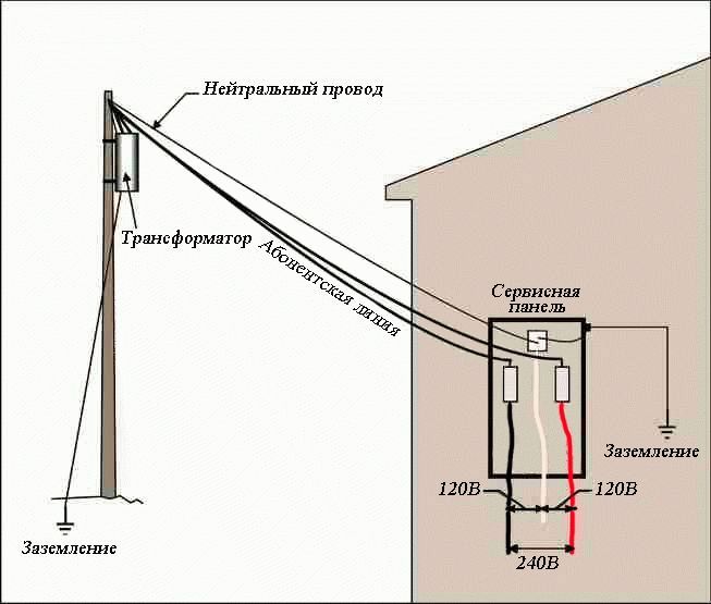
But at the input we have two wires left, connected via the TN-C system. At the transformer substation, the neutral is grounded, phase L is suitable through the air, and another core, which combines neutral protection with the working wire, is marked on the PEN diagrams. Your own ground loop should now be connected to your home network. There are two ways to do this:
- convert the system from TN-C to TN-C-S;
- connect via TT system.
In a two-wire TN-C system there is no separate protective conductor. To convert it to TN-C-S, we divide the combined PEN wire into two separate ones: protective PE and working N. To determine it, we will use an indicator: on the phase one it will glow, but on the PEN we need there is no glow.
We install a busbar in the electrical input panel, metallic connected to its body. It will serve as a PE grounding bus; we connect the PEN wire to it, which comes from the street. We install two more busbars in the shield, isolated from the housing. We make a jumper to one of them, this will be the bus of the neutral working wire N. We connect phase L to the second isolated bus.
The use of the TT system does not require separation of the PEN wire. With this scheme, there is no electrical connection between the ground loop and the PEN conductor. Two wires enter the house through busbars isolated from the power supply housing. The electrical panel itself is grounded.
TT has advantages over the TN-C-S system, which requires separation of the PEN wire. If the zero is burned off from the input side of the TN-C-S system, all devices will be grounded to the circuit, which under some circumstances may cause negative consequences. With the TT system, the PEN wire does not have any connection with the home grounding, and there is guaranteed to be no voltage on the device housings.
The use of a CT circuit requires the mandatory presence of RCDs - residual current devices. They will also be useful in the TN-C-S system. They will be especially useful in situations where there is an uneven phase load and a small voltage appears on the neutral conductor. When the network is electrically connected to the protective conductor, it may also appear on the device body. That's when the protection should work.
From the above we conclude that for a house with old wiring the best option is to use a TT circuit, and it is better to mount separate connections inside for grounding powerful devices.