Jet stove from a gas cylinder. Self-production of a rocket-type stove Drawings of a rocket stove from a gas cylinder
close ×
The rocket stove was used by many peoples of the world long before the advent of modern home and household stoves. It served, first of all, to heat the home and provide a warm sleeping place in the house. Cooking also played an important role. When developing the stove design, it was necessary to come up with a system that could operate with the highest possible efficiency when loading low-quality wood fuel (dry and wet).
Nowadays, it is used for heating, for cooking, and also as an interior element. You can make a rocket stove with your own hands using almost improvised materials. It all depends on its purpose and the place where it will be used.
Types and designs rocket furnace many - from the simplest to the multifunctional. For efficient work It is necessary to follow some rules for operating the furnace structure. There are 2 main principles of operation of a rocket stove, regardless of its configuration:
- free circulation of released gases from the fuel through the formed furnace channels, without manual drafting of the chimney;
- post-burning of pyrolysis gases released from fuel combustion under conditions of insufficient oxygen supply.
Design, characteristics and application
The rocket stove owes its unique name to the characteristic stove hum that can be heard throughout the combustion process. It vaguely resembles the sound of a rocket taking off. It is also similar to a rocket in that, during the combustion process, jet thrust is created in it. The cone-shaped shape of the stove can also be associated with the name, but this is not the main characteristic.
There are 2 types of stove designs (shown in the diagrams):
The simplest rocket oven
The simplest design of a direct combustion rocket stove consists of 2 pipes connected by an outlet - a Russian rocket stove.
The down tube is separated by a metal plate. The top of the pipe is approximately 2/3 of common space, where the main fuel is directly placed. The lower part serves as a primitive blower, which provides air exchange in the furnace.
The fuel filling in this case is horizontal. When laid vertically, a rocket-type furnace consists of two vertical pipes of different lengths, and a third horizontal one, which serves as a connecting channel. The latter performs the function of a firebox.
The simplest form of a jet stove is installed, usually outdoors, for the purpose of cooking food and heating water.
To make a stationary simple rocket stove made of brick, a material is used that is installed on a heat-resistant platform.
In order to achieve higher productivity, new elements were added to the simplest stove design.
 The diagram shows a camping jet stove. The lower pipe is divided by a special jumper into a fuel compartment (2) and a compartment for venting air into the combustion area (3). The upper part of the furnace consists of a riser pipe, around which a heat-insulating composition (4) is laid, covered with an outer metal casing (1).
The operation of the stove is as follows: fuel that heats the stove (straw, paper) is placed in the fuel compartment, after which the main fuel is added (chips, twigs, etc.). During active combustion, hot gases are formed, rising along the riser and escaping out. A stand for cooking utensils is installed on the cut of the pipe, taking into account a gap of 7-10 mm. Otherwise, if the required gap is not maintained, the outlet for oxygen draft will be blocked, which, in turn, raises hot gases upward. The combustion process will stop.
If the conditions for creating air draft are met, even with the combustion door closed, the combustion process will not stop. Here, the second principle of operation of a long-burning rocket furnace partially works - afterburning of pyrolysis gases in conditions of insufficient oxygen supply.
For this principle to work fully, it is necessary to provide the rocket furnace with high-quality thermal insulation of the secondary combustion chamber, because the processes of formation and combustion of gases require compliance with temperature requirements.
Improved design
This type of rocket stove, in an improved configuration, can be used at home both for cooking and for heating rooms. In addition to the fuel compartment and pipe, it has a second body, on top of which a hob is installed, and the chimney is routed to the street. You can heat a room with an area of up to 50 sq.m. with such a stove.
As a result of the modernization, useful qualities and efficiency increase due to the fact that the long-burning rocket stove acquires several unique and important properties:
- Unlike the simple design of a rocket stove, the improved one uses a second outer casing, thermal insulating material around the combustion pipe, and a hermetically sealed upper part of the casing, which creates conditions for maintaining a high temperature long time;
- an autonomous hole for supplying secondary air in a modernized furnace provides optimal air supply, while in a simple design an open firebox is used for this;
- the chimney system is designed in such a way that the heated gas flow does not rush out of the pipe immediately, but passes through the stove channels, ensuring high-quality combustion of secondary fuel, heating of the hob and uniform heat transfer of air into the room through the heated stove body.
The improved design uses additional elements aimed at creating high heat transfer and versatility of the rocket stove. Two principles of furnace operation are actively involved here. First, preliminary combustion of solid fuel occurs, which during combustion releases pyrolysis gases, which are used as secondary fuel.
 The operating principle of a rocket furnace of this design is depicted in detail in the diagram on the left. Fuel for preliminary combustion is loaded into the fuel compartment (1). In the zone of the most active heat exchange (2), under conditions of insufficient supply of primary oxygen (A), regulated by the damper (3), pyrolysis gases are released. They rush to the end of the fire channel (5), where they burn out. Favorable conditions for gas combustion are created due to the high thermal insulation of the structure and the continuously flowing flow of secondary oxygen (B).
Then the hot gas rises up through the internal channel of the riser pipe (7) under the housing cover, which is often equipped under the cooking surface (10), due to continuous high-temperature heating. There, the gas accumulation diverges through channels located between the riser and the outer furnace body (6). Under conditions of constant heating of the housing, its walls accumulate heat, causing the air in the room to heat up. After this, the gas flow descends down the channel and then exits upward into the chimney pipe (11).
The combustion process can last several hours. For maximum heat transfer from the furnace and complete combustion of pyrolysis gases, it is necessary to maintain a consistently high temperature in the riser. To do this, it is placed in a pipe of slightly larger diameter, which is called a shell (8). The resulting space between the two pipes is tightly filled with a heat-resistant compound, for example, sifted sand, to provide thermal insulation in the pipe.
Features of operating a rocket furnace
- Before loading the main fuel, the stove must be warmed up. This applies more to large and multifunctional rocket stoves. They do not require pre-heating. thermal energy will be used idle.
- To accelerate the furnace, dry paper, wood shavings, and straw are placed in an open ash pit. Sufficient heating of the furnace can be determined by the hum in the furnace, which subsequently subsides. Then the main fuel is placed into the heated rocket stove, which is ignited by the booster fuel.
- At the beginning of combustion of the main fuel, the ash door is opened completely. After a while, when the stove hum appears, the vent is covered until the hum is replaced by a whisper. In the future, to assess the state of combustion of the stove, you also need to focus on the “stove sound”, opening the ash door slightly when it subsides and closing it when a hum occurs.
- The larger the reaction furnace, the smaller the inlet opening fresh air necessary. It is advisable to use a separate blower in such a furnace.
- The power of the furnace can be adjusted only by the volume of fuel added, but not by the air supply.
- When making a large rocket stove yourself, its bunker should be made with a tight-fitting lid, without gaps or cracks. Otherwise, stable operating conditions of the furnace will not be ensured, which can result in the consumption of excess fuel energy.
- Contrary to popular belief, a rocket stove for a sauna is not suitable for installation, since the stove does not emit infrared radiation in sufficient quantities, which is necessary for heating the walls and transmitting convection into the air masses in a sauna. A rocket stove for a bathhouse, theoretically, can only be installed using the Shirokov-Khramtsov stove type, the characteristics of which are given below.
- A rocket stove for a garage is a mobile version of a stove design that can quickly heat a room. The main element is a heating tank made of pipe.
Fuel types
With proper assembly and operation, a rocket stove can be fired with any type of solid fuel, wood and its waste. For example, branches, leaves, firewood, coal, corn stalks, cones, pieces of chipboard, pieces of furniture. Fuel can be loaded into the stove in either dry or raw form. This is especially true for its operation in natural conditions, where it is not always possible to find dry raw materials.
Types of rocket stoves
A rocket stove can be made independently or custom-made from various materials. Here you need to focus on the capabilities and available resources.
Gas cylinder stove
 Used gas cylinder is a widely used stove material. The convenience of its use lies in the fact that it is, in fact, a ready-made blank of the furnace body of an elongated cone shape. Fuel costs are minimal, and the heat generated will heat a room up to 50 sq.m. The material of the cylinder must be chosen that is non-explosive and resistant to high temperatures and heat. Best option is a propane cylinder made of solid metal, with a capacity of 50 liters, a diameter of 35 cm and a height of 85 cm. This volume is enough to burn any type of fuel.
Also, for the manufacture of a portable rocket stove from a gas cylinder, volumes of 12 and 27 liters are used, but with less heat transfer. The cylinder can be purchased at a special gas station.
Before starting the manufacture of the furnace, the gas is released from the cylinder by opening the valve for a while. Then, a simple potbelly stove is made. Next, the upper part of the cylinder is cut off, leaving the hole for the valve. A round hole with a welded steel strip is cut at the top, which serves as the basis for the chimney.
Brick oven
It can be either stationary or traveling. A rocket stove made hastily, in 15-20 minutes, made of bricks, broken bricks or cobblestones “on dry ground” will do an excellent job of cooking food and heating water. The disadvantage of such a stove is low fuel economy and low heat output. Heating the bricks in the chimney to 1000 degrees allows the structure to quickly enter operating mode. At the same time, the rocket does not smoke due to the fact that at this temperature all the fuel burns without residue.

Water-jacketed rocket stove
The most commonly used is the stationary oven type. The peculiarity of such a stove is that heat transfer is used not only to heat the air in the room, but also to heat the water. To do this, a rocket stove with a water circuit is connected to a heat storage tank to create a system autonomous water supply. An ideal option for use in a country house or private water supply, because the device helps reduce heating and water heating costs, which is very economical.

Barrel stove
 A common model for heating a home. Low-cost to manufacture and energy-intensive in heat transfer. Often equipped together with a warm bed. Capable of heating a room of more than 50 square meters. m. A standard 200-liter barrel with a diameter of 607 mm is perfect for making a stove. This diameter can be reduced by almost half, which is convenient for installing a riser pipe made from a gas cylinder or tin buckets with a diameter of 300-400 mm. In short, the stove can be built from scrap materials.
Shirokov-Khramtsov furnace

Domestic modernization of the rocket furnace. The main material is heat-resistant concrete, which creates excellent thermodynamics in the structure. Due to the stable operation of the furnace and the low thermal conductivity of the material, part of the heat comes out in the form of infrared radiation, which is impossible when using other types of furnace. If you use heat-resistant glass, the stove can be converted into a fireplace. The disadvantage of installing such a furnace is the high cost of the material, the preparation of which will require a concrete mixer.
Stove-oven
For cooking and preparations at home and outdoors, an improved stove design with a wide cooking surface for installing several containers is installed. A vertical riser pipe with a firebox welded to it is located directly under the hob, providing high-temperature heating. Accumulating under the panel cover, the gases exit through a horizontal pipe, uniformly heating the entire area of the panel, and rush to the exit through a vertical chimney channel.

How to make it yourself
Let's take a closer look at making a do-it-yourself rocket stove with a stove bench. Its design is more cumbersome and installation is more difficult than the types of stoves listed above, but thanks to step-by-step instructions and diagrams, building it yourself will not be difficult. The main thing is to follow all installation recommendations.
Step-by-step instructions on how to make a rocket stove:
- First, make a 10 cm deepening to install the fuel compartment, lining it with fireclay bricks. Then you need to install the formwork along the structure line. For a stronger foundation, you can use construction reinforcement or mesh, laying it on a brick base.
- Using a level, lay out the base for the combustion chamber.
- Then you need to fill the structure with concrete and let it dry for 24 hours. After the solution has set, you can continue building the furnace.

- Lay out the base of the stove, laying the bricks in a continuous pattern.
- Form the side walls by laying several rows of masonry.
- Arrange the lower channel of the rocket, taking into account the order.
- Then you need to lay a series of transverse bricks so that the riser pipe and combustion chamber remain open, and the combustion chamber remains hidden.

- You need to take the body of the old boiler and cut it on both sides so that you end up with a pipe that is wide in diameter.
- A flange is installed in the lower part of the housing from under fuel and lubricants, into which a horizontal heat exchanger pipe will be installed. In order to maintain the tightness and safety of the product, it is necessary to provide for the use of continuous welds in the work.

- After this, the outlet pipe cuts into the barrel. The barrel is cleaned from rust, covered with a primer and several layers of heat-resistant paint.
- A side branch must be welded to a chimney located horizontally to form an ash pan. To facilitate its cleaning, when operating the furnace, the channel must be equipped with a sealed flange.
- Next, a fire pipe is laid out of refractory bricks, maintaining dimensions of 18x18 cm square. When laying out the internal channel, it is important to maintain strict verticality for stable operation of the furnace. To do this, you can use a body kit or a level.

- It is necessary to put a casing on the flame tube, and place perlite balls in the resulting space. The lower part of the riser must be sealed with a clay mixture to prevent spillage of the thermal insulation.
- Then the fuel cap is made using a previously cut part from the boiler. For convenience, you can weld a handle to the lid.
- Mix clay mortar with sawdust (prevents the product from cracking), up to 50% of the total volume. The result is the so-called “adobe grease”, which needs to be coated with the appearance of the resulting structure to mask unsightly parts and increase thermal insulation.

- Next, the appearance of the furnace is formed. The furnace circuit is laid out. For this you can use different materials: stone, brick, sandbags. The inner part is filled with crushed stone, and the upper part is covered with adobe mixture.
- A 200-liter barrel, which serves as the outer shell of the furnace, is installed on a previously prepared base. Be sure to install the barrel so that the lower pipe is on the side of the stove bench. Next, the lower part is covered with clay to seal it.
- Then you need to form a channel from a corrugated pipe to supply air from the street and bring it to the fuel compartment. Without installing such a channel, a DIY rocket stove will consume warm air from the room during operation.

- After the construction of the main part of the stove structure, training kindling is carried out to check the free removal of gases through the horizontal chimney.
- The heat exchanger pipes are connected to the lower pipe, installed on a red brick base.
- Next, you need to install the chimney pipe yourself, hermetically sealing all connections with asbestos cord or fire-resistant coating.
- At the end, the bed needs to be shaped in the same way as before - when forming the main body. If you leave the barrel open, without masking it with adobe, then the heat during combustion will immediately enter the room. If the barrel is completely covered with adobe, leaving the lid intact, then heat will accumulate in the body, which will create excellent conditions for cooking food on hob.

Instead of a barrel, you can use a gas cylinder (a rocket stove made from a gas cylinder), and instead of a boiler, pipes and tin buckets adjusted to the shape. When creating a rocket stove with your own hands, it is very important to maintain accuracy and proportionality in size using drawings. This will guarantee long and efficient operation of the long-burning stove with your own hands.
The advantages of using homemade rocket stoves in everyday life are significant. The construction of a furnace does not require large economic costs (for materials, heating) and time (it takes a maximum of 3-4 days to manufacture a furnace).
High performance and heat transfer with unpretentious fuel loading are ideal. You can decorate the stove in any way you like, thereby adding a new interior element to your home.
© When using site materials (quotes, images), the source must be indicated.
A stove made from a gas cylinder will turn out to be more economical and efficient than manufacturing equal in complexity from other available materials. The shape of the gas cylinder itself will help. The quality of a stove is largely determined by its firebox. The ideal firebox in all respects is spherical. Considering that the firebox must have at least 2 openings - an inlet, for loading fuel and supplying air, and an outlet, for the exhaust gases to exit into the chimney, the optimal shape of the firebox is not a very long and narrow cylinder with rounded ends, and that’s what the cylinder is. Its shape is chosen based on the need to maintain greater pressure with minimal metal consumption, but the result is the same.
What kind of stove can be made from a cylinder?
Since the shape of the firebox is optimized on the most general basis, then cylinder stoves can be very different - from flaming combustion to sophisticated designs, which, as they say, turn the eyes of even an experienced heating engineer. This article examines several furnaces, arranged in increasing order of manufacturing complexity; their purpose is also taken into account:
- for residential premises.
- Heating systems for non-residential premises.
- Summer cooking.
- Universal small-sized portable emergency; stove just in case.
The need to minimize the cost of additional materials and the ability to make a stove with your own hands without complex tools and/or technological operations are also taken into account. Of course, a prerequisite is sufficient convenience and safety of use. Unfortunately, it is impossible to give recommendations on the legalization of homemade stoves: fire regulations for them are very strict. Here everyone needs to resolve the issue on the spot, as best they can. Or not to decide at all: building stoves yourself is not prohibited anywhere, but possible consequences will fall entirely on the author/owner.
Note: the requirement of maximum simplicity and low cost does not apply to the rocket stove described at the end. However, this stove not only heats a large room using wood chips, but also allows you to get a real warm bed at home without building a brick stove. And the costs of materials and labor required are several times less.
Which cylinder should I look for?
First of all: the stove requires an all-metal cylinder. Composite explosion-proof ones are not suitable, they are not heat-resistant. A 5-liter household cylinder (item 1 in the figure) is definitely not suitable for the main part of the stove: it’s too small. The ratio of its surface to volume will give such heat loss that it will not be possible to completely burn any fuel. Making additional thermal insulation is not worth the trouble. The complexity of the work, the cost of materials, the dimensions and weight of the furnace will increase so much that all the work loses its meaning.

Note: The only possible use of a 5-liter cylinder is a fuel tank for a liquid fuel stove. Two of these will be discussed below.
12 and 27 liter cylinders (items 2 and 3) allow you to make a stove just in case, which can also be stored in the pantry of a city apartment. From a 12-liter one as a stove you can remove a thermal power of 2-3 kW, and from a 27-liter one – 5-7 kW.
The best preparation for the stove is the most common 50-liter propane cylinder with a diameter of 300 mm and a height of 850 mm (item 4). Its volume is already sufficient for efficient combustion of any fuel by any known method, and its weight and dimensions do not yet complicate the work. In addition, there are many such cylinders in use that are still in good working order, but have exhausted their service life according to the specifications; they can be bought inexpensively. Most of the stoves described below are made from just such cylinders.
Note: if you have a choice, you should use a cylinder with a valve rather than a valve. The valve makes an excellent stove power regulator by supplying air (air throttle).
As for the common 40-liter cylinders for industrial gases (item 5) with a caliber of 240 mm, they are poorly suited for the furnace: although the walls made of thick durable metal will ensure the durability of the furnace, the cylinders themselves are too narrow, heavy and bulky. A good powerful stove, up to 100 kW or more, could be made from a 12- or 18-inch professional cylinder, but they are rare, expensive, and not every healthy man can shoulder such an empty one.
In principle, it would be possible to make camp stoves from small 2-10 liter industrial cylinders, but again, the metal is thick, durable, difficult to work with, and the stove itself will be too heavy. There are, however, in the population of small special balloons some exotic individuals that make excellent ones; We will talk about them later.
From simple to complex: balloon stove

You probably guessed even earlier that the simplest homemade stove from a gas cylinder is an emergency backup stove, 12 or 27 liters. You can use a 50-liter stove on it, but such a stove will no longer fit in a city pantry. A balloon potbelly stove will not be able to regularly heat several generations: the relatively thin metal of the body of a household cylinder will burn out. But it’s quite possible to heat a shed with it from time to time or stay on it until it’s warm.
The design is extremely simple, see fig. Of the purchased components, you only need a firebox door or a monoblock from the firebox/blower room. Theoretically it works as much as possible here optimal shape a thick, curly cylinder: a cylinder potbelly stove does not need a grate with an ash pan, or any internal partitions. One thing that is necessary, like any potbelly stove, for good heat transfer is a horizontal chimney elbow made of a metal pipe with a length of 2-2.5 m.
Note: the chimney diameter of a 12-liter potbelly stove is 60 mm, a 27-liter stove is 80 mm, a 50-liter stove is 100-120 mm.
Balloon cooking
Gas cylinders make good grills. They also burn fuel, but these are no longer ovens, but culinary technological equipment, and quite a lot has been written about it. Therefore, we will not dwell further on gas-cylinder cooking. However, those interested, as they say, without leaving the cash register, to find out how to make a barbecue grill from a cylinder yourself, can watch the video:
About pyrolysis
In all of the following designs of cylinder stoves, pyrolysis is used to one degree or another - decomposition under the influence of high temperature of heavy organic compounds into light, volatile and flammable ones. Pyrolysis allows you to burn everything that, in principle, can burn, completely - up to carbon dioxide and water vapor. It is hardly possible to build a furnace with an efficiency of more than 70% without pyrolysis.

One of the main parameters of the pyrolysis process that must be taken into account when developing a furnace is the degree of its complexity. Simply put, this is the number of thermochemical reactions required to break the original complex and heavy molecules into those capable of burning to completion.
Pyrolysis of heavy flammable liquids (eg used motor oil) usually occurs in 2-3 stages. Wood fuel breaks down into easily combustible gases in a multi-stage process, and its complete pyrolysis requires 5-6 times more time than in a liquid fuel stove.
Since the exhaust gases, under the influence of draft, move from the combustion center into the chimney, pyrolysis ends at some distance from the firebox. For oil furnaces it is insignificant, about 10-15 cm, and in them pyrolysis can be combined in space with afterburning of pyrolysis gases. This condition is also true for coal stoves; volatile components of coal are released and disintegrate easily.
For complete pyrolysis of wood fuel, a gas-flame path length of about 1 m is required, and in its space it is necessary to distinguish, physically or implicitly, 3 zones (chambers): the firebox itself (gasifier), where the fuel burns and primary pyrolysis gases are released, a secondary gasifier (reactor ) with a supply of secondary air (secondary air), where pyrolysis is completely completed, and an afterburner, also with a secondary supply, where light gases are completely burned. These conditions must be taken into account when designing a wood stove.
Oil garage
The next most difficult, costly and labor-intensive method is from a balloon. This product is in great demand: you can heat a garage with such a stove for nothing, but there is no large-scale production; firemen prohibit it. Let us briefly recall the principle of its operation.

The oil burns quietly in the fuel tank; air is supplied here in doses using an air throttle. Here the heat of its combustion goes mainly to evaporation. The vapors rise into a vertical gasification column, or reactor. The reactor walls are perforated; outside air because the pressure in the entire furnace duct due to the draft of the chimney is lower than atmospheric.
The influx of air sharply increases the combustion of oil vapors, the temperature rises and pyrolysis begins. The pyrolysis products also begin to burn, causing the temperature to rise even more; in the middle part of the reactor it can reach 1300 degrees. At this temperature, nitrogen oxides are formed in noticeable quantities. Nitrogen oxidation is an endothermic reaction; it consumes a significant part of the fuel energy. However, nitrogen oxidation is useful in this case: it protects the furnace from overheating and explosion; The rate of formation of nitrogen oxides increases sharply with increasing temperature, according to a power law.
In the upper part of the reactor, the pyrolysis gases have almost burned out and there is a large excess of air. For complete afterburning in the column, it would have to be made several meters high and solid, without perforation, but then the nitrogen oxides would have passed the peak of their temperature instability and carried a noticeable share of the fuel energy into the pipe. To avoid this, gases from the reactor are released into an afterburner or afterburner.
The afterburner is divided approximately in half by an incomplete partition. Directly in front of it, pyrolysis gases burn out, maintaining a temperature that prevents the stabilization of nitrogen oxides. Behind the partition, all the oxygen in the air is already consumed, but the temperature here is still above 700 degrees. Now nitrogen oxides decompose with the release of energy back into nitrogen and oxygen, which is used for afterburning of the remaining pyrolysis gases; the energy release of these 2 processes maintains an approximately constant temperature in the afterburner.
The outlet to the chimney from the afterburner is located away from the partition, but it is enough to move it 15-20 cm away from it: thermochemical reactions in oil gases proceed quickly. Already completely burnt gases with a temperature of about 400 degrees go into the chimney, which ensures the efficiency of the furnace up to 80% and higher.
Typically, for furnaces used for exhaust from cylinders, a 50-liter propane bottle is used, cut in a ratio of 2:1, a third goes to the tank, and 2/3 to the afterburner, pos. 1 in Fig. From such a stove you can remove up to 30 kW of heat, but there are also plenty of emergency situations with a serious outcome from them.

However, the magazine “Behind the Wheel” has long ago published the design of a garage furnace for working off with a power of 5-7 kW with a reservoir from a 5-liter cylinder. With such a low power, it was possible to combine the reactor with an afterburner into a single fully functional column:
- In the lower cone of the column, the gases expand and the temperature drops to a value sufficient for pyrolysis, but almost eliminating nitrogen oxidation.
- The perforation of the column is rare and the air flow through it is in slight excess.
- In the upper cone, the gases are again retained for a time sufficient for complete combustion at a power of up to approximately 8 kW.
Nitrogen oxides are still formed in this furnace, but in negligible quantities, ensuring only automatic adjustment of the furnace mode. Operational power control is ensured by a rotary valve on the filling neck, which is also an air throttle.
This furnace can be significantly improved if there is a 10 or 12 liter industrial cylinder with a caliber of 150 mm and a height of 800/900 mm. These most often sell helium for inflating balloons. The profitability of the balloon business reaches 400%, but it most often takes place on temporary promotions, and the shelf life of a balloon filled with helium is limited and short: helium is the second record holder after hydrogen for diffusion speed. Therefore, completely serviceable helium cylinders are often sold cheaply.
Note: We do not recommend trying to run a helium business alone. All over the world, the flower and holiday mafia has firmly laid its paw on him, which, they say, even Cosa Nostra bypasses.
The design of a “helium-propane” 2-cylinder furnace for mining is shown in pos. 4. The thick walls of the cylinder distribute heat more evenly along its height, and the dome at the top and the narrow, 60-80 mm outlet into the chimney trap gases more effectively than a cone. Therefore, the perforation of the column and, accordingly, the air flow can be increased, obtaining a power of 10-12 kW. A maximum filling of 3.5 liters is enough for 3-4 hours of operation at full power.
At the same time, you can improve the fuel-air system. A standard cylinder valve is perfect for the throttle; you just need to extend it from the inside with a thin-walled steel tube, pos. 4a. You can simply screw it, as much force as you can, onto the part of the fitting protruding inward: the landing thread on it is tapered, so it will grab tightly.
It is better to make the filling fitting retractable and sliding in the neck, pos. 4b. Through the extended fitting, the stove is ignited and the fuel level is monitored. And when it is retracted, it is relatively safe to add oil while the oven is running.
If the stove is constantly heated, then it is still advisable to remember about sappers, for whom the most dangerous is not the first, but some N-th mine. You can completely guarantee against an emergency with a stove by arranging a fuel supply from a separate feed tank or just a feeder, pos. 5. The height of the feeder should not exceed the maximum permissible fuel level in the tank (for a 5-liter tank this is approximately 2/3 of its height), and the feeder must be located at least 0.5 m from the stove. This way you can control the fuel level and refuel the stove as you please. In addition, the volume of the feeder can be any, only its height is limited, so it is quite possible to adapt a tank for it with refilling for a day or more.
"Long" stoves
In this case, this metaphor does not mean stoves made from recumbent industrial cylinders, but from ordinary 50-liter wood fuel stoves. In the long-term burning mode, wood undergoes pyrolysis, which greatly increases the efficiency and duration of heat transfer of stoves. The fuel in them (from dry sawdust and weeds to fragments of antique furniture) burns in a thin layer from the surface, which is why “long” stoves are sometimes called surface burning stoves.
Pyrolysis can occur either in a physically limited separate volume with subsequent combustion of pyrolysis gases in an afterburner (these are furnaces with separate combustion), or the pyrogen gases immediately evaporate into a large, well-heated buffer chamber, where pyrolysis is completed and the pyrogen gases burn, these are co-combustion furnaces. To ensure high efficiency of both, it is highly desirable to heat the air entering the pyrolysis zone.
Bubafonya

An example of a long-burning furnace with separate combustion is the widely known one. In it, pyrolysis is concentrated under the “pancake” oppression. The diagram of the bubafoni device is shown in Fig. right; As the fuel burns, the air duct with the pancake moves down. Much has already been written in detail about the operating principles and features of making bubafons, so we will only note the following:
- The efficiency of a homemade bubafon can exceed 85%, and the duration of heat transfer from one load of fuel can reach a day.
- Fuel for bubafoni needs to be room-dry with a humidity of up to 12%
- It is permissible to add fuel to the bubafon while moving, but you cannot stop it; for maintenance/repair work you need to wait until the load is completely burned out.
- The diameter of a 50-liter bottle of 300 mm is the minimum acceptable for bubafoni, so this stove must be made from it carefully and with a full understanding of the matter.
Bubafonya is a very economical stove and is well suited for heating garages and households. premises. Its design is simple and can be made at home. On to the next rice. The main stages of the work process and dimensions are shown specifically for balloon bubafoni with a power of up to 5-6 kW. You just need to add that the gaps for air supply between the main (closest to the air duct) ends of the blades must be kept the same. When welding, instead of a jig, it is convenient to use suitable scraps of metal - pieces of rod, etc. The blades are first grabbed from the outside, and then, after removing the “conductors,” they are cooked to the end.

Note: The power of the bubafoni can be adjusted within a wide range, up to 10 times, but only manually, because The air throttle can only be installed at the upper end of the air duct, which is movable.
Slobozhanka
The Slobozhanka combined combustion furnace is even simpler in design and not inferior to the bubafon in terms of parameters, diagram in Fig. right. But it’s hardly worth making a slobozhanka from a balloon because its minimum permissible diameter is about 500 mm and a balloon slobozhanka will not show good efficiency. In addition, all Slobozhanka stoves have very serious disadvantages:

Construction of the Slobozhanka stove
- Extremely toxic gases accumulate under the roof of the stove; if you open the stove lid while moving, you can be poisoned to death.
- There is no way to stop the Slobozhanka: if you close the throttle, the stove will pull air back through the chimney before choking. The pressure in the furnace will exceed atmospheric pressure and the toxic mixture will come out.
- A hard, dense carbon deposit settles on the hearth or grate of the furnace, as in all “long” furnaces. After about a year (this is with good fuel), it grows to the mouth of the air duct, and it is difficult to knock it down and in easily accessible places.
Beautiful stranger
Most other homemade “long” stoves are no better, but more complicated than bubafoni. But there is one, almost purely pyrolysis stove (which is rare with wood), worthy of attention; its drawing is shown in Fig. In addition, this furnace is also a bunker, which allows wood stoves also rare.

According to the principle of operation, the “stranger” is a simplified and truncated rocket stove, about which see next. section The retention of pyrogases in the afterburner under the hob is achieved by a diaphragm in the chimney, in exactly the same way as washers distribute coolant from the heating main to consumers. In the furnace business, such a constructive technique is rare, because any weakening of draft deteriorates the quality of the stove, but in this case the creators turned evil into good.
How? Power limitation: this is an exclusively summer-country cooking stove. It’s only enough for cooking, although you can squeeze several times more out of a 50-liter bottle. But the “stranger” works on any flammable garbage that can be pushed into the bunker; best - on fairly long chips, branches and dry stems, and it is much more economical, cheaper, simpler and lighter than the simplest brick slab. A foundation here, of course, is not needed, and a chimney with a height of 1.5-2 m is sufficient. The furnace is ignited from the top, through the neck of the gasifier or the loading hatch, using a flammable liquid.
The authors of the “stranger” cannot be denied knowledge of heating engineering, but with metal they were a little too clever: separate, and even removable gasifiers under the stoves and vault (the bottom-grate and partition in the original) are simply not needed here. The bottom can be the bottom of the 50-liter cylinder itself with the same 20-mm hole in the center, and the ash pan can be placed in its skirt. The outlet pipe of the gasifier is welded onto the dome of the cylinder, and the afterburner can be made from a piece of 300 mm pipe or sheet metal. In this case, it is quite possible to clean the stove through the fuel bunker and the gasifier outlet.
The crown of creation, or...
Emela never dreamed of it
The crown of balloon-stove creativity is, without a doubt, the rocket stove, see fig. But not only and not so much because doing it according to all the rules requires considerable (albeit uncomplicated) work, attention, ingenuity and accuracy. The main thing is that the rocket stove was purposely created for a 50-liter bottle, although most often it is made from a barrel. Not only the shape, but also the dimensions of a 50-liter propane cylinder are optimal for this stove: if a rocket from a barrel heats a horizontal section of the chimney in a stove bench (hog) up to 6 m long, then a balloon one, with a drum capacity four times smaller (see below for details) - up to 4 m. It’s unlikely that anyone will need a bed of this length, but the rocket hog can be made from thin-walled metal corrugation, laying it in a wave-like pattern in the mass of the bed. This, of course, will greatly increase both the efficiency of heating the room and the duration of heat transfer after heating, which can reach 12 hours.

The advantages of a rocket stove do not end there:
- This is a stove that not only burns long, but also continuously burns. Additional fuel can be added while the furnace is running without restrictions.
- The rocket stove can also be stopped and re-ignited without restrictions, and the ignition itself is simply simple: with paper, straw or shavings, like a fire.
- The rocket stove breathes, just like .
- Unlike brick stoves, a rocket stove is almost insensitive to long breaks in the firebox during the cold season.
- Acceleration of a newly built or standing rocket stove is also simple: heating with paper, shavings or straw until the stove becomes warm to the touch.
- The foundation of the rocket furnace is not needed: although its weight is under a ton, the support area is large and the load from the furnace on the floor does not exceed the permissible 250 kg per square meter according to SNiP. m.
The rocket stove has only 2 disadvantages, and, as they say, not fatal. Firstly, after kindling and, possibly, during the combustion process, it is necessary to set the stove mode by adjusting the air supply. If the stove makes a loud noise, this does not mean that it heats better. On the contrary, in this mode the gas-air path quickly becomes overgrown with carbon deposits; A correctly heated stove whispers quietly.
Secondly, the furnace power is regulated only by the amount of fuel loading. On-line power adjustment is generally impossible; Only the oven mode is set by air supply. While driving, you can not only add more fuel to increase power, but also pull out individual smoldering wood chips with tongs and immediately extinguish them, but this is a fire hazard.
Note: if “at a whisper” the stove seems to be heating weakly, it doesn’t matter, wait until the heat goes into the battery. The oven will release it later, cooling down after heating. If you need to quickly warm up, without thinking about fuel consumption yet, open the air until it starts to hum. It is not advisable to bring it to a loud roar; the carbon deposits inside will settle heavily.
How does a rocket work?
The design and principle of operation of a rocket stove. Here we recall the most important things.
The idea of a rocket furnace “on fingers” is as follows: imagine 2 physically connected processes with an efficiency of less than 100%; Let's say 90% each. For the 2nd to occur, the products of the 1st are needed. If they are launched simultaneously together, then due to mutual interference caused by entropy, the final efficiency will not exceed 65%. And if you “scroll” the 1st one first, save its results somewhere and then run the 2nd one on them, then the maximum overall efficiency will be slightly more than 80%.
In the most general sense, this is a universal law. It is thanks to him that the market economy, with all its bulky and gluttonous financial, administrative and power superstructures, turns out to be more effective than a natural economy. In a rocket stove, this law is technically implemented by the sequential inclusion of 2 stoves, one that generates heat and one that stores and heats.

The stove-generator consists of (see Fig.) a blower 1a with an air supply regulator (it sets the stove into operation), a fuel hopper 1b with a blind lid, a channel for supplying secondary air 1b to ensure complete combustion of the fuel, a flame pipe (fire pipe) 1d and internal or primary chimney - riser - 1d. The fire duct cannot be made too short or long: it must, on the one hand, heat the secondary air well, without which complete combustion of wood pyrogen gases cannot be achieved. On the other hand, in a fire pipeline that is too long, the gases themselves will cool down and pyrolysis will not reach completion. The entire generating stove is securely wrapped in high-quality thermal insulation with the lowest possible heat capacity. All that is required of the primary furnace is to completely burn the fuel and release a stream of burnt hot gases from the riser.
Note: from an efficiency point of view, the optimal internal diameter of the riser is 70 mm. But if you want to achieve maximum furnace power, then you need a riser pipe with a diameter of 100 mm; then its shell needs not 150, but 200 mm. In this case, the efficiency decreases slightly. Further, when describing the technology for constructing the furnace, the dimensions are given for both cases.
The basis of the heating-storage part of the furnace is a high-capacity heat accumulator, but it is impossible to immediately release gases from the riser into it, their temperature is about 1000 degrees. There are good heat-resistant heat-storing materials, but they are very expensive, so the authors of the rocket stove used adobe as a storage device. Its heat capacity is enormous, but it is not heat resistant, so the secondary furnace must start with a high-grade to mid-grade heat converter, with temperatures up to 300 degrees. In addition, part of the primary heat must be released into the room immediately to compensate for current heat losses.
All these functions are performed by the furnace drum, and a 50-liter cylinder will be used for it. Gases from the riser enter under the cover of the drum 2a with the cooking surface 2b. The drum is thin-walled metal, it transfers heat well into the room. Having rolled under the lid, the gases enter the annular lowering of the drum between its tube 2g and the metal shell of the riser insulation 2v. Under the drum 2d is also metal; the metal does not allow flue gases into the insulation of the primary furnace.
The fact is that inexpensive and high-quality insulating materials are porous. If you let flue gases reach them, their pores will be drawn in, they will quickly become clogged with fumes, and all the insulation, and with it the efficiency of the furnace, will go down the drain. Adobe is also porous and is also very easily spoiled by carbon deposits. Therefore, the primary task when building a rocket stove is to ensure complete tightness of the gas and smoke duct.
In the drum, approximately 1/3 of its height from the top, the gases have already cooled enough to transfer their heat to the storage tank. From this height to the bottom, the lining (coating) of the entire stove with adobe begins. In the drum, the flue gases release, outward and into the storage tank, approximately half of the heat generated by the generator, but it is too early to transfer them to the heat exchanger: from the drum, through its outlet, 2e gases enter the secondary ash pan 3a with a sealed cleaning door 3b, and then into a long horizontal section of the chimney (hog) 4. From the hog, the gases that almost completely gave up heat into the adobe bed are released into the ordinary external chimney.
Why is a secondary ash pan needed? The gases coming out of the drum are not very hot and are already chemically neutral, because burned out to the end. But they still contain a small amount of solid suspension; mainly microparticles of mineral components of wood. And the hog, as mentioned above, is made of thin metal fiber and is also laid with twists, and this entire pipe is tightly walled up, so it is impossible to clean the hog. If you let dirty gases into it, the gap will soon become overgrown with soot and the bed will have to be broken. And in the secondary ash pan, the suspension settles. Once or twice a year it will have to be raked out, but the stove will now last for many years.
So now we know enough to start building a rocket stove. That's what we'll do.
Building a rocket
First, we need to stock up on 5 types of linings. However, their components are either inexpensive or just lying around, and it’s not difficult to prepare the mixtures yourself:
- 5a - the most common adobe: clay, thoroughly mixed with finely chopped straw and mixed with water until the dough becomes thick. Because the bed was not blown or saklya, except for its weight it is not loaded with anything and is located indoors, the quality of the clay does not matter much, you can take a self-dug gully one.
- 5b – main heat insulator. Medium-fat oven clay in half with crushed stone from light fireclay bricks ШЛ. Water until the dough becomes thick.
- 5v – heat-resistant, gas-tight, mechanically strong coating. Regular fireclay sand with oven clay 1:1 by volume. Water until it reaches the consistency of plasticine.
- 5g – self-dug sand, river or ravine, or very thin sandy loam. No washing or calcination is needed; just sift through a 3 mm sieve.
- 5d – medium-fat oven clay.
Some clarifications. It is better to introduce grass straw into adobe (meadow grass hay), with it the strength, which we do not really need, will be lower, but the heat capacity will also be greater. As for the recipes for making adobe, choose any suitable one; for a rocket stove it is not important. You can do it as in the video below, but we don’t need to build the entire house.
Video: making adobe
Mixture 5b requires crushed stone (not sand!) and only SL. Other fireclays (ShM, ShV, etc.) are themselves good heat accumulators; it’s not without reason that they are used to make stove fireboxes. But in this case, a large heat capacity will only do harm. It is advisable to add more crushed stone, as long as the clay glues it together.
The purpose of the 5v mixture is to extend the life of the stove. All metal structures in it are made of steel with walls up to 3 mm thick, so that the rocket “flies” properly. But in the heat path, thin metal will quickly burn. However, by that time the 5B coating will have been fired, and over time, sections of steel pipes will spontaneously be replaced by ceramic ones. True, then the stove will have to be cleaned carefully (the riser, although slowly, still becomes overgrown with carbon deposits), after all, it is fragile.
5g contains a fairly large admixture of alumina. IN construction sand it is undesirable, so they get rid of it. But alumina is just right for the lining of the riser: the heat capacity of the mixture is minimal, and when sintered, it will also gain some strength. And they get the raw materials for free.
Note: The riser can also be lined with composition 5b, but, firstly, it costs money. Secondly, the work will take a lot of time - you will have to line it in layers, with the previous layer completely drying, otherwise the coating in the shell will dry for an inordinately long time and the inside will certainly crack.
Stage 0
First you need to make a bed for the stove, see fig. – a durable wooden trestle bed of the required configuration. Its frame is made of intersecting quarter-mortise logs (beam 100x100 mm) with a mesh of at least 600x900 mm under the stove and at least 600x1200 mm under the stove bench itself. The oblong cells of the frame are oriented along the bed. The curved edges of the frame are brought to the contour using scraps of timber and boards.

Note: There is no need to raise the bed any higher; taking into account the power of the lining of the bed, it will be convenient.
The frame is covered with 40 mm tongue and groove boards. The joints of the deck boards should be oriented perpendicular to the long sides of the frame cells. The ends of the beams and boards protruding beyond the desired contour of the bench are sawn down to shape immediately, but its outer contour remains free for now; it will be lined with plasterboard, etc. upon completion of the furnace construction.
Before assembly, parts are first impregnated with biocide, and the entire structure is impregnated twice with a water-polymer emulsion. The frame parts are fastened at the crosshairs with diagonal pairs of 6x90 mm confirmats, and the flooring boards are attached to the frame with longitudinal pairs of 6x60 mm confirmats, a pair in a board for each longitudinal joist.
Then, at the place where the stove is permanently installed, 4 mm mineral cardboard is laid on the floor with some margin for cutting along the contour, and the place above which the stove itself will be is additionally covered with a sheet of roofing iron; it needs to be cut to shape in advance, taking into account that the extension before the furnace fire must be at least 100 mm, this is enough for a rocket.
Now the bed is moved to its place. An exit to the outer chimney is immediately arranged, somewhere at the rear edge of the bed. Its lower edge should be 70-90 mm above level A of the furnace lining (see figure with the main diagram), i.e. 120-140 mm from the level of the bed flooring.
Stage 1
On the bed along the entire contour, a strong formwork of height A is made, according to the basic layout of the furnace (40-50 mm), with a smooth top edge. If the bed is adjacent to the wall, the formwork is brought up to the walls, and the level of its top is beaten along them with a cord. Then the formwork is filled with adobe and its surface is smoothed with a polish - a flat, smooth board with a rounded corner. If the formwork is incomplete and it is inconvenient to guide the far end of the glaze along the mark, you can still lean beacons made of strips of plywood against the walls; they are removed when the adobe dries, and the cracks are filled in.
Stage 2
While level A is drying, let's start making a drum from a cylinder, see fig. First, cut off its top so that a hole with a diameter of 200-220 mm is obtained (don’t forget to vent the remaining gas!), It is covered with a steel round 3-4 mm thick, this will be the hob. Then they make a cut below the top welding seam of the cylinder by 40-50 mm, this is almost the lid.

A thin sheet metal skirt is welded to the lid. Its side seam also needs to be welded; it will take the skirt away from the seam connection. Cook at a direct current of 60 A with a 2-mm electrode. I must say that holding the arc in this mode is quite difficult; you need to be a fairly experienced welder. After installing the skirt, holes are drilled in it for M4-M5 bolts, 3-6 holes. evenly around the circumference, 20-25 mm from the bottom edge.
The third cut of the balloon is below the bottom seam, where the tube begins to turn into a rounded bottom. There is no need to remove the remnants of the balloon skirt, as this will only hold it more firmly in the stove. Now at the bottom of the tube we make a cutout for its outlet in the form of a horizontally elongated rectangle. Its height is 70 mm, and its width depends on the chosen riser pipe, see the inset at the top right of the main diagram.
The next operation is laying the sealing gasket. It requires a braided asbestos cord; woven shaggy twine is not suitable. The cord is glued with superglue or, better, “Moment”. Then the glue, of course, will burn out, but the gasket will stick to the residue, especially since the cover will have to be removed once a year, not every year.
Having laid the gasket, immediately, as soon as the glue has set, we put on the lid and place a load of 2-3 kg on it. Under load, we mark the location of the hole in the tube. After removing the cover, drill and tap the thread. Now we insert the tube into the inverted lid and measure the depth of the drum, this is necessary to clarify the height of the riser pipe. We separate the lid from the tube so that the gasket is not soaked through with glue and the cord does not lose its elasticity, stage 2 is completed.
Stage 3
Level A will take a week or two to dry, and during this time we will work on the combustion part of the furnace. Parts 1a, 1b and 1d from professional pipe 150x150 mm; 1D riser pipe is round. When marking workpieces, you must observe the distance indicated on the main diagram from the rear edge of the hopper, when viewed from the side of the blower, to the front edge of the drum. Within the specified limits, it is arbitrary, based on the location of the furnace and its design. The forward movement of the blower is also arbitrary, but, of course, within reasonable limits. There is no need to push the blower under the bunker either, the valve will be hot. The best option is to cut the blower flush with the front edge of the bunker, as in the diagram.
After cutting out the holes for the hopper and riser pipe, the first step is to weld in the secondary partition. air channel 1c, at a height of 30 mm from the bottom of the firebox. A full seam is not needed, 2 clamps through the not yet welded rear end of the firebox, 2-4 through the hole for the hopper and 2 through the ash pan are enough. Material – sheet steel 1.5-2.5 mm.
Note: The tilt angle of the bunker can be within 45-90 degrees from the horizontal. But when tilted at 45 degrees, rough wood chips can get stuck, and if the bunker is vertical, then when adding fuel, your hand ends up dangerously close to the hot drum. Therefore, a slope of 60 degrees was chosen.
The rear edge of the air baffle should be flush with the front edge of the riser pipe hole. Its front edge should protrude outward by 20-25 mm. This shelf is needed to avoid littering when cleaning the stove: this design does not allow the use of a grate with a retractable ash pan, and the ash will have to be scraped into the tray; its edge is slipped under the shelf. However, the rocket furnace produces nothing but ash.
It is better to make the blower valve with a vertical stroke in grooves with flat springs; a rotary door will not ensure proper smooth adjustment of the furnace mode, and a throttle with a rotary damper is more difficult to make. The hopper lid is bent from galvanized steel. There is no need for complete tightness here, as long as it fits tightly.
When the combustion metal structure is ready (don’t forget to weld the riser pipe and weld the back of the flame pipe!), it is lined with a 5B compound in a layer of 10-12 mm, as shown in the diagram. Continuous coating is given only along the bottom. The top and sides of the blower from its front edge to the hopper are left free. Having been lined, they are placed to dry.
Dry by putting the blower part on the pole. At first, they inspect it regularly: if the coating slips, it is removed and a new portion is made from thicker clay and with less water. Do not rely on chance, this is a responsible operation!
Stage 4
The combustion part will dry out soon (2-3 days), and during this time it is quite possible to make formwork for insulation and lay its bottom layer, because Level A adobe has already dried enough to hold a small amount of weight. The design of the formwork is clear from Fig. The meaning of what is marked in red will become clear later. Formwork is made from boards or plywood 20-25 mm thick. There is no need to firmly fasten the parts, because... the formwork will then have to be dismantled. Thin wire brackets on the outside at the corners are sufficient; You can just cover it with tape.

The formwork is put in place with the outer edge of the front plank level with the edge of the bed and exactly along the axis of the future stove. You need to install it carefully, with measurements, otherwise the parts of the stove will not fit together later. You can prevent accidental displacement with thin pointed pegs, sticking them into the adobe from the outside. The beacons along which the bottom layer of insulation will be aligned are made of any material, but their height must be exactly equal to that of the front formwork strip.
Stage 5
The formwork is filled with mixture 5b to level B. The filling surface is leveled with a glaze along the beacons and the front strip.
Stage 6
While the insulating pad dries out and the combustion part dries out, we make the shell of the riser and under the drum. With the shell, everything is simple: either a piece of pipe, or we bend it from a thin (1-2 mm) sheet. Both, of course, are made of steel. If the shell is made of sheet metal, the seam can be folded; a perfect circle is not necessary.
Note: there is no need to make a shell below the riser pipe and then use clay (see below) to round the top of the riser. The stove works better if the gases flow into the lower part with a bend.
Under the drum, as can be seen in the diagram, is inclined. This is necessary for better flow turbulence in the secondary ash pan, see below. But if you thought: “Well, now we’ll cut out an ellipse within an ellipse!”, then you’re in vain. With a tilt of 10 degrees, the major axis of the ellipse turns out to be as much as 304.5 mm, but we need a smaller one, 5-7 degrees.
That is, we make the outer diameter of the hearth blank (steel sheet 2-3 mm) 4 mm smaller internal diameter drum, and the diameter of the cutout for the shell is 3 mm larger than its outer diameter, and will fit like original. After installing the hearth, we will coat the cracks along the outer and inner contours (marked with green circles in the diagram) with 5d clay, bringing the sausages into the fillets simply with your finger.
Stage 7
We check whether level 5B is completely dry. This can be done by temporarily removing the front formwork strip. If not, we take a smoke break (sorry, we are fighting nicotine. We drink juice.) for a day or two.
If it’s dry, we put the furnace part into the formwork; its coating is probably already dry. It is also necessary to place it exactly along the axis of the furnace, vertically and horizontally, with measurements: the drum and shell should ultimately be concentric plus or minus 2 mm, and the top of the secondary ash pan (see below) fit tightly under the upper edge of the drum outlet. We set the front edge of the blower flush with the outer edge of the formwork and, accordingly, the bed. At the same time, it will protrude from the insulation to the thickness of the formwork board, this is just enough to then smear it with adobe on the outside: the insulation used is effective, but also sensitive to air humidity.
We fix the exposed combustion part with pegs, just like the formwork. Let them remain in the mass of isolation, no big deal. Now we install additional front panels and fill the formwork to the top with mixture 5b, this is where we have reached the level G of the lining. It is no longer necessary to completely level it, so as not to accidentally catch the bunker protruding from the solution. It is enough to iron it with a polish, resting on the edges of the formwork, in the area where the drum is located, marked in pale gray on the formwork diagram. But here you need to level it until smooth.
Stage 8
We dry level G. This is also a responsible operation; you cannot rely on the microclimate of the room and conventional drying by natural evaporation to the outside; the oven will turn out bad and short-lived. It is necessary to create more or less stable conditions inside the drying mass.
This is done with a regular 40-60 W incandescent light bulb. It (turned on, of course) is inserted into the firebox so that the flask is under the riser pipe. You just need to provide some kind of mini trestle for the lamp socket so that the bulb does not touch the metal, otherwise the glass may burst. The top of level D will dry enough to withstand further operations while we make the secondary ash pan, see next.
Note: the light bulb will have to burn continuously for a total of approximately 30 days, taking into account further stages of drying. During this time, the 60-watt one will consume 24x30x0.06 = 43.2 kW/hour of electricity, and the 40-watt one will consume 28.8 kW/hour, which will cost 129 rubles respectively. 60 kopecks and 86 rub. 40 kopecks Whether such an expense is exorbitant is up to you to decide. However, on any side it is better to take 40-watt. Drying will take longer, but it will be of better quality and less sensitive to the quality of the raw materials.
Stage 9
We make a secondary ash pan, or just an ash pan for short, because... There is no primary in this furnace. Here it is similar in appearance to the same unit in the American prototypes of rocket stoves, but differs fundamentally from them.
In the Americans, an almost laminar flow of gases enters the ash pan through the wide outlet of the drum, but here it is twisted for deeper cleaning, see next. stage of the ash pit installation diagram. The cause of the vortices is the rotation of the Earth; more precisely, the Coriolis force caused by it, the same one that spins the water flowing from the bathtub.
Note: military-historical oddities. At the end of World War II, the Nazis developed the V-3, an ultra-long-range multi-chamber cannon with a gradual acceleration of the projectile, to shell London. They made adits in the rock and assembled the entire system. And then it turned out that the Germans, famous for their thoroughness... forgot to take into account the rotation of the Earth! All the shells would have missed. So the V-3 never fired, causing only panic in Western intelligence agencies and a wave of myths that has reached this day. Later, Saddam Hussein floated around with the same idea. He was going to shoot from his desert at Berlin, Paris and the same London. His specialists have already calculated everything accurately and conducted successful experiments on small models. But, again, after everything it turned out that all modern technologies are not capable of creating precision-precision gun barrels 200-300 m long. In general, work loves a fool. Even if the fool is smart and knows a lot.
Drawings of the ash pit are shown in Fig. Dimension L is measured from point A (marked in red on the formwork diagram) along the perpendicular (red arrow there) to the edge of the bed. Dimension H is the sum of the heights of the formwork measured locally and the exit window already cut in the drum (70 mm if cut accurately). The bevel of the top of the ash pan back is arbitrary within reasonable limits, as long as it does not later stick out from under the coating of the drum with adobe.

Walled ash pan box - made of thin steel sheet or galvanized 0.6-1.2 mm. The front panel (face) is made of steel sheet 4-6 mm, because it can be exposed from the outside and has M5 threaded holes for attaching the cover. The cutout for the chimney bur is along the outer diameter of the existing metal flue; 150-180 mm is suitable for this stove. Its location is arbitrary, you just need to observe dimensions A, B and C on the drawing of the ash pit. All parts except the hog are connected by welding continuous seam in the same mode as for the drum cover skirt. For the addition of a hog, see below.
The cover of the cleaning hole measuring 180x180 mm is also made of steel with a thickness of 4-6 mm. The sealing gasket underneath is made of mineral cardboard. Mounting bolts – from M5x8 to M5x15 with hex heads. Bolts with any splines should not be used: the inside of the ash pan becomes overgrown with a thin layer of dense soot. The thickness of its layer will soon stabilize, but the bolts to remove the cover have to be unscrewed with a socket wrench with a crank.
Note: It is not advisable to use a hinged door with a latch - it will not provide a seal forever. You won’t notice it right away, but the stove’s appetite will increase and it will begin to become overgrown with smoke inside. And you have to open the ash pan for cleaning at most once a year if the stove is heated with room-dry wood.
Stage 10
We must assume that while we were fiddling with the ash pan, level G had already dried out. You can check by temporarily removing the formwork wall, as well as level B. If ready, install the drum and ash pan.
Replace the drum tube without the lid. We make sure that it and the riser pipe are concentric, and also that the exit window is in the right place, see the inset at the top right on general scheme furnace and diagram in Fig..

We put a little mixture 5b inside the drum and use a spatula to form a wedge from it with an inclination of 5-7 degrees, converging to the outlet window. Now we put it in place under, and press it into the solution with a stick. We select the mortar from the cutout under the shell, otherwise you won’t be able to install the shell, the mortar is on crushed stone. Next, we install the shell, turning it slightly. We coat the gaps along the external and internal contours with 5d clay, as described earlier.
Stage 11
There is no need to wait for the insulation under the floor to dry; we immediately line the riser. We fill the shell layer by layer, 5-7 layers in total, with a 5g composition (home-dug sand or thin sandy loam). We compact each layer with a rolling pin with an even end and spray it with a spray bottle until a crust forms. Not reaching 5-6 cm to the top, we form a plug from 5d clay. When it dries, thin cracks form between it, the pipe and the shell, but that’s okay: when the furnace is fired, they will soon be overgrown with soot from the density and strength of the concrete.
Stage 12
Immediately after installing the drum, install the ash pan; We will close the cleaning hole with a lid later. Installing it is simple: on the lower and large side surfaces we apply a layer of 5d clay 2-3 mm thick. We insert the ash pan into place, press and press down. Then we coat the contour of the drum output window (also known as the input ash pan) on the outside with the same 5d clay. Smear the sausages squeezed inside into fillets with your finger. Don’t lose sight: the edge of the hearth protrudes into the ash pan as a narrow segmental shelf; a fillet must also be formed under it. In general, the transition from the drum to the ash pan must be sealed both inside and outside (green oval on the general diagram of the furnace).
Stage 13
If the level G of the insulation has not yet completely dried, we wait for it to dry. To speed it up, the formwork can already be removed. If so, we also remove the formwork (drying continues, the light in the firebox is still shining!) and apply insulation with a 5B solution to level B. We apply it without formwork, by hand. Manually, without much precision, we form a semicircular arch at level B.
Stage 14
Without waiting for level B to dry, we make formwork along the contour of the bed, as when forming level A, but already to level D. Now we clarify its value according to measurement data: above the upper edge of the hole for the bur in the ash pan there should be at least 80 mm. It is also undesirable to do more than 120 mm; the heat transfer of the stove after heating will be sluggish. New level Let's call G for brevity G1.
Stage 15
We fill the new formwork with adobe to the bottom edge of the hole for the bur in the ash pan, on one side. On the other - to the lower edge of the exit to the outer chimney. We level it roughly with our hands, but we need to make sure that there are no dips and, accordingly, U-shaped sections of the hog. If you read carefully at the beginning, you will understand that we will be able to lift the hog from the ash pit to the chimney by 10-30 mm. It is necessary for uniform heating of the bed, but downward sloping areas of the hog are undesirable in any case.
Stage 16
We stretch the prepared corrugation to its full length. We insert one end of it into the ash pan by 15-20 mm and flare it from the inside with a flat screwdriver through the cleaning door. We coat the outer contour of the hog's input into the ash pan with 5d clay, as already described.
Next, we cover the beginning of the hog, counting from the ash pan, by 15-25 cm with adobe; it will keep the corrugation from being pulled out during the following operations. Now we lay the hog in the bed with bends, but not coming closer than 100 mm to any edge. As you lay, lightly press down, pressing lightly into the adobe. Having laid it, we insert the far end of the corrugation into the exit hole into the chimney and, again, coat the contour with 5d clay.
Stage 17
We manually cover the hog with adobe so that there are no gaps or niches under the bottom of the corrugation. Then we fill the formwork with adobe and smooth its surface with a polish. If the adobe is thick, heavy, and made from oily clay, you can immediately form roundings on the upper corners, see the inset at the bottom right of the main diagram. It is convenient to do this with a strip of galvanized steel, bent with a trough to a quarter of a circle. If the adobe is light, you will have to dust it with a milling cutter or circle around the stone during final finishing.
Stage 18
We constantly put the ash pan and drum lids in place. The light in the firebox is still on, drying out! We attach the drum cover with screws with conical heads: when tightened tightly, they will tightly compress the gasket between the cover and the tube.
Stage 19
We form the adobe coating of the drum, as already said: 1/3 of its top remains free, and counting down from half its height, the adobe layer should be no thinner than 100 mm. As for the rest, as God pleases, here the rocket stove will tolerate any design.
Stage 20
At the end of drying (this is about 2 weeks), remove the formwork and round off the remaining corners, if necessary. The last operations before kindling are to paint the drum with heat-resistant enamel at 450 degrees (750 degrees is much more expensive), and cover the stove bench with acrylic varnish in 2 layers; 2nd after complete drying of the 1st.
The varnish will not prevent the stove from breathing; the breath will flow through the bed covering. But, firstly, the varnish will prevent the adobe from collecting dust. Secondly, it will protect it from accidental moisture. Thirdly, it will give the stove the noble appearance of glazed clay.
Final stage: rocket launch
In a dry oven, we place the blower valve in the grooves without pushing it in (the light bulb is no longer there, of course), close the hopper lid and heat it with paper, straw, shavings, etc., all the time feeding fuel through the blower. When the bed feels at least a little warmer to the touch, add more light fuel and load the standard fuel into the bunker. Having waited until the stove hums quite loudly, we close the vent “to a whisper.” That's it, the rocket stove with a stove bench is ready! Now - off to the start! That is, in bed.
In conclusion
There is a direction in balloon-stove creativity that is still being developed only by smokers, and then somehow: the construction of stoves from 2 or more cylinders. And from the point of view of heating engineering, its prospects are quite serious.
Old non-autonomous diving equipment was divided into 2 classes based on the number of helmet attachment points: three-bolt with a soft suit for working at depths of up to 60 m and heavy, hard 12-bolt deep-sea. The profession of a shallow-water diver has absolutely official name it was a three-bolt diver. In this regard, I wonder what hidden meaning the trolls and goblins of the Runet would see in the name, well, let’s say: “Society of Multi-Cylinder Stove Makers”?
Today, quite a lot of varieties and models of wood-burning stoves have been developed and implemented. In this series, the do-it-yourself rocket stove, the drawings of which will be presented below, fully meets all expectations. Such a heating structure certainly deserves close attention, as it has some specific advantages that are indispensable in certain conditions.
This version of a wood-burning stove is simple and original in design and does not require a large number of expensive components and materials for production. Install such a stove by making it on our own, probably anyone can do it, even if they have no experience in constructing such structures, but can read the provided drawings and work with some tools.
It is interesting to note that, if necessary, a rocket stove can be made even in 20–30 minutes, for example, from an iron can. However, if you make every effort, it is possible to get a comfortable stationary structure for your home with a heated couch that can even replace an ordinary sofa. At the same time, a rocket stove will not require complex arrangements, like bell-type or Russian stoves, which are massive structures.
Operating principle of the rocket stove
The rocket stove was originally conceived as one of the functional items for survival in difficult conditions. Therefore, its design had to meet certain criteria:
- Efficient room heating.
- Possibility of cooking.
- High efficiency of the device when used for heating of various wood fuels of any quality.
- The ability to add fuel without stopping the combustion process.
- In addition, the stove had to retain heat for at least 6-7 hours to allow the owners to spend the night in comfortable conditions.
- Maximum safety of the structure, in terms of eliminating the possibility of leakage into the room carbon monoxide.
- Another condition that had to be met was the simplicity and accessibility of the design for its manufacture by any non-professional.
Therefore, we took as a basis basic principles several types of heating devices using wood solid fuel:
- Free circulation of heated air and gases through all channels. The stove operates without forced air, and the draft is created by a chimney that draws out combustion products. The higher the pipe is raised, the more intense the draft.
- The principle of afterburning gases released during combustion from fuel (pyrolysis), which is used in long-burning devices. This operating principle is extremely important due to the high efficiency of the device, which is achieved by creating special conditions for the afterburning of pyrolysis gases for the most complete use of the energy potential contained in the fuel.
The term “pyrolysis” means the decomposition of solid fuel into volatile substances under the influence of high temperatures and simultaneous “oxygen starvation”. Under certain conditions, they are capable of burning, also releasing a large amount of thermal energy. It is important to know that the pyrolysis of insufficiently dried wood takes quite a long time in the gas phase, that is, the released pyrolysis gas will require a lot of heat to create a mixture (wood gas) that can burn completely. Therefore, it is not recommended to use wet fuel for a rocket stove.
Variety of rocket stoves - from simple to complex
The simplest design of a rocket stove
In a simple design of a rocket stove, heated by bunches of branches or splinters, combustion products are almost immediately sent into the chimney, without having time to form flammable wood gas in the stove body, so it will not be possible to heat the room with it. Such ovens can only be used for cooking. This model is manufactured in stationary and mobile versions; it only operates on the principle of free circulation of heated air, since the required conditions are not created in it for a full-fledged pyrolysis process.
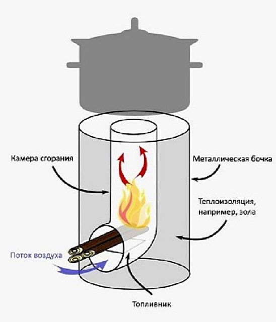
In such furnaces, a small section of pipe is used as a fuel chamber. It can have a horizontal position, as shown in the diagram, or be turned upward. In the latter case, fuel is loaded vertically.
After igniting the fuel placed in the pipe, the heated gases released from it rush up the vertical section of the pipe to the outside.

Containers for cooking or heating water are installed on top of the vertical pipe. To ensure that gases escape freely and the bottom of the container does not completely block the draft in the pipe, a special metal stand is installed on top of the stove. She creates gap of the required size, which Helps maintain cravings.

On top is a very original stand for a container with heated water
By the way, this simplest type of furnace device was the first to be invented, and because of the upward opening of the firebox and the flame escaping from it, the furnace most likely received the name rocket. In addition, if the combustion mode is incorrect, the structure emits a whistling “rocket” hum, but if the stove is configured correctly, it rustles quietly.
Advanced Rocket Stove
Since it is impossible to heat the room using the simplest rocket stove with a free outlet of gases, the design was later supplemented with a heat exchanger and smoke exhaust ducts.

After the improvements, the entire operating principle of the rocket stove has changed somewhat.
- To maintain the high temperature of heated air in a vertical pipe, it was insulated with fire-resistant material, and then covered on top with another metal casing made from a larger diameter pipe or a metal barrel with a closed top.
- A door was installed on the opening of the firebox, and a separate channel for secondary air appeared in the lower part of the furnace. Through it, blowing began to take place (necessary for afterburning pyrolysis gases), which previously occurred through an open firebox.
- In addition, the chimney pipe was moved to the lower part of the body, which forced the heated air to circulate throughout the body, going around all the internal channels, rather than going directly into the atmosphere.

- The combustion products, which have a high temperature, first began to rise to the ceiling of the outer casing, accumulate there and heat it, which made it possible to use the outer horizontal surface as hob. Then, the flow of gases cools down and goes down, turns into an elbow and only from there goes into the chimney pipe.
- Thanks to the intake of secondary air, gases are burned at the end of the lower horizontal channel, which significantly increases the efficiency of the furnace. The free circulation of gases creates a self-regulating system that limits the flow of air into the combustion chamber, since it is supplied only as the hot gases cool under the “ceiling” of the housing.

A very popular scheme is from metal profile and an old gas cylinder
The stove model shown in the figure operates like a “stove stove” and has a chimney leading outside. However, it is unsuitable for use in residential premises, since, due to changes in external pressure, reverse draft may occur, which will contribute to the entry of carbon monoxide into the room. Therefore, such a stove should always be supervised, and it is most often used for heating utility rooms or a garage.
Rocket stove with a warm bed
A rocket stove with a stove bench is also constructed on the principle of afterburning pyrolysis gases, but in this version the heat exchanger is a structure of combined long channels coming from the stove and laid or formed from non-flammable plastic materials under the surface of the stove bench.

It should be noted that such a heating system is by no means new, and, in fact, such a rocket stove has a fairly rich history. It was invented a long time ago, presumably in Manchuria, called “kan”, and is still traditional for peasant houses in China and Korea.

Similar stoves called “kan” have long been used to heat homes in East Asia.
The system is a wide bed made of stone, brick and clay, inside which The air heated in the stove passes through the arranged channels, which are essentially an elongated chimney. Passing through this labyrinth and gradually giving off heat, the gas flow, cooling, exits into a chimney with a height of 3000 ÷ 3500 mm, located on the street, next to the house.
The stove itself is located at one end of the stove bench and, as a rule, is equipped with a hob, which allows it to be used for cooking.
The top of the stone-clay structure “kan” is covered with straw or bamboo mats, or a wooden flooring is placed there. At night, the couches were used as beds, and during the day - in the form of a seat, on which, traditionally for Asian peoples, a special low table 300 mm high was installed - meals were taken behind it.
This heating system is quite economical in terms of fuel consumption, since to heat it it is enough to use a medium-thick branch. Such a rocket stove is capable of retaining heat for a long time, creating comfortable conditions for sleeping throughout the night.

And Korean “ondol” stoves probably became the prototypes of modern “warm floors”
Korean homes use a heating system similar to “kan”, which is called “ondol”. This heating option, unlike the Chinese one, is installed not inside the couch, but under the entire floor of the house. In principle, it can be argued that this method of transferring and distributing heat into living spaces seems to form the basis for the design of the modern “warm floor” system.
Furnace design with connected the pipes to it can be clearly seen in the diagram presented.

Nowadays, with the modern rich variety of materials, the channels in this furnace design can be made of metal pipes laid in the form of a coil and well insulated with non-flammable materials. Therefore, the last section of the chimney system can exit from the structure of the stove next to the stove itself or at the end of the stove, and then go through the wall into a chimney installed on the street.
In the presented diagram you can see the results of the design work, which made it possible to achieve a relative simplicity of the scheme, which has high efficiency, and also meets all the requirements for a speech rocket.

Fuel is loaded vertically into the combustion hole. Then it is set on fire, and, burning out, gradually settles down. The air that supports combustion enters the bottom of the combustion chamber through an opening that acts as a blower. It must provide sufficient air flow for afterburning of the released products of thermal decomposition of wood. But, at the same time, there should not be too much air, since it can cool the initially released gases, and in this case the process of afterburning the pyrolysis gases will not be able to take place, and the combustion products will settle on the walls of the housing.
In this version, the vertical loading furnace has the chamber has a blind cover, which will eliminate the risk of gases entering the room when creating reverse draft.
In a completely isolated volume of released gas, thermal energy is generated, temperature and pressure rise, and thrust increases. As the fuel burns, the burning gases escape through the channels of the furnace body into the heat exchanger, heating the internal surfaces along the way. Since the channels have a complex configuration, gases are retained inside the furnace for a longer time, giving off heat to the body and surfaces of the channels, which, in turn, they heat the surface of the couch and, accordingly, the room itself.
Over time, any furnace and its ducts require cleaning of soot deposits. In this design, the problem area is the heat exchanger pipes located inside the bench. In order to carry out these preventive measures without any problems, a hermetically sealed cleaning door is installed at the level of rotation of the heat exchanger from the furnace body into the pipes under the stove bench (indicated in the diagram as “Secondary Airtight Ash Pit”). It is in this place that all unburnt products of thermal decomposition of wood concentrate and settle. The door is periodically opened and the passages are cleared of soot - this process guarantees long-term operation of the chimney. In order for the door to close tightly, asbestos gaskets must be secured to its inner edges.
How to properly heat a rocket stove?
To get maximum effect heating, it is recommended to preheat the stove before adding the bulk of the fuel. This process is carried out using paper, dry shavings or sawdust, which are set on fire in the firebox. When the system warms up, it will change the sound it makes - it may fade out or change its tone. The main fuel is placed into the heated unit, which will ignite from the heat already created by heating.

Any firewood and even thin branches are suitable for the rocket stove, but the main thing is that they be dry.
Until the fuel burns well, the combustion chamber or ash door must be kept open . But only when the fire becomes intense and the stove begins to hum, the door is closed. Then, during the combustion process, the access of air from the ashpit is gradually blocked - here you need to focus on the tonality of the sound of the stove. If the air damper accidentally closes and the intensity of the flame decreases, it must be opened slightly again and the stove will flare up with renewed vigor.
Advantages and disadvantages of the rocket stove
Before moving on to a description of the manufacturing process of a rocket stove, it is advisable to summarize information about its advantages and disadvantages.
Rocket stoves are quite popular due to their positive qualities , which include:
- Simplicity of design and small amount of materials.
- Even a novice master can make any of the furnace designs, if desired.
- The construction of a rocket stove does not require the purchase of expensive building materials.
- Undemanding requirement for forced chimney draft, self-regulation of stove operation.
- High efficiency rocket furnace with a pyrolysis gas afterburning system.
- Possibility of adding fuel while firing the stove.
Despite the large number of advantages of this design, its operation also has a number of shortcomings :
- When using the simplest design of a rocket stove, you can use only dry branches and splinters, since excess moisture can cause backdraft. In a more complex device system, the use of damp wood is also not recommended, because it will not provide the required temperature for pyrolysis to occur.
- The rocket stove cannot be left unattended during combustion, as this is very unsafe.
- This type of device is unsuitable for heating a bathhouse, since it does not give off enough heat in the infrared range, which is especially important for a steam room. A rocket stove with a stove bench can only be suitable for the recreation room of a sauna building.
Video: special opinion on rocket stoves
Making a rocket stove with a stove bench
Rocket stoves can have different sizes, and a variety of materials are used for their manufacture - these are metal pipes, barrels and gas cylinders, bricks and clay. It is quite acceptable and combined option, consisting of pipes, stones, clay and sand. It is he who deserves special attention.

From a gas cylinder you can make a stove that is simple in design, including using it for a version with a stove bench.
How to make a simple stove itself is more or less clear from the drawings presented above and the description of its operation, so it is worth considering the manufacture of a heating unit, specifically equipped with a stove bench.
Video: homemade rocket stove from a gas cylinder
You might be interested in information on how to do it with step-by-step instructions
To make it completely clear what and where is located in the design of the rocket furnace, this diagram will be used to describe the work.

So, the rocket stove in question consists of the following elements:
- 1a– a blower with an air supply regulator, with the help of which the oven is adjusted to the desired mode;
- 1b– fuel chamber (hopper) with a blind lid;
- 1c– a channel for supplying secondary air, ensuring complete combustion of pyrolysis gases released by wood;
- 1g– flame tube 150÷200 mm long;
- 1d– primary chimney (riser), with a diameter of 70÷100 mm.
The flame tube should not be made too long or short. If this element is too long, then the secondary air in it will quickly cool down and the process of afterburning the pyrolysis gases will not reach completion.
The entire structure of the flame pipe and riser must be thermally insulated as efficiently as possible. The task of this unit is to ensure complete combustion of pyrolysis gases and supply hot masses from the riser to other channels, which will already transfer heat to the room and to the bench.
It should be noted here that in order to obtain optimal efficiency from the furnace, the diameter r The azer should be made with a size of 70 mm, and if the goal is to achieve maximum furnace power, then it should be made with a diameter of 100 mm. In this case, the length of the flame tube should be 150÷200 mm. Further, when describing the installation of the furnace, dimensions will be given for both cases.
It is impossible to immediately pass heated air from the riser into the heat accumulator, since its temperature reaches 900÷1000 degrees. High-quality heat-resistant heat-accumulating materials have a fairly high price, therefore, most often, adobe (clay mixed with chopped straw) is used for these purposes. This material has a high heat capacity potential, but is not heat resistant, so the design of the secondary furnace (cylinder body) begins with an air temperature converter, which must be heated to only 300 degrees. Part of the generated heat is immediately released into the room and replenishes current heat loss.
The described functions are performed by the furnace body, made from a standard 50 liter gas cylinder.
- 2a– furnace body cover. Heated air enters under it from the riser;
- 2b– a cooking surface that is heated from the inside by heated gases escaping from the riser;
- 2v– metal insulation of the riser (shell);
- 2g– heat exchange channels. Heated gas enters them, diverging under the ceiling of the housing;
- 2d– lower metal part of the body;
- 2e– exit from the housing to the cleaning chamber.
The main task when arranging these parts of the furnace is to ensure complete tightness of the smoke exhaust line.
In the housing (drum), at a height ⅓ from its “ceiling”, the gases cool down and already have normal temperature to enter them into storage. From approximately this height to the floor of the room, the oven thermally insulated several layers of different compositions - this process is called lining.
- 3a– the second cleaning chamber, through which the heat exchanger (“hog”) located under the stove bench is cleaned of carbon deposits;
- 3b– sealed door of the second cleaning chamber;
- 4 - “hog”, a long horizontal section of the chimney located under the stove bench.
Having passed through the “hog” pipes and almost completely transferred the heat to the adobe bench, the gases escape through the main chimney channel into the atmosphere.
Having understood the structure of the rocket furnace in detail, you can proceed to its construction.
Construction of a rocket stove with a stove bench - step by step
First of all, you need to prepare lining compounds. Their components will cost very little, since they can often be found completely free, literally right under your feet:
- 5a– adobe. As mentioned above, this is clay mixed with chopped straw and mixed with water until the masonry mortar becomes thick. Any clay for making adobe is suitable, since it will not be exposed to external atmospheric influences;
- 5b– oven clay mixed with crushed stone. This will be the main heat insulator. The mortar should have the consistency of a bricklaying mixture;
- 5v– heat-resistant lining made of oven clay and fireclay sand in proportions 1:1 and having the consistency of plasticine;
- 5g– ordinary sifted sand;
- 5d – medium-fat clay for stove masonry.
Step-by-step work on the design is carried out in the following sequence:
Bed for the couch
Having prepared all the necessary compositions, a bed is made - a durable wooden shield of the required configuration. Its frame is made of timber with a cross-section of 100×100 mm. Frame - with cells measuring 600x900 mm under the stove and 600x1200 mm under the stove bench. If a curvilinear shape of the bed is planned, then it is brought to the desired configuration with the help of boards and scraps of timber.

The bed is a frame base for the further construction of the furnace structure
The frame is sheathed with a tongue and groove board 40 mm thick - it is fixed across the long sides of the frame. Later, after the installation of the stove is completed, the side façade of the bed will be covered with plasterboard. All parts of the wooden bed structure must be impregnated with biocide and then painted twice with a water-based emulsion.
Next, on the floor, in the place of the room where the stove will be installed, mineral cardboard (cardboard made of basalt fibers) 4 mm thick, the size and shape completely corresponding to the parameters of the bed, is laid. Directly under the stove, a sheet of roofing iron is fixed on top of the cardboard, which will extend 200–300 mm from under the stove in front of the firebox.
Then, the bed is transferred and firmly installed on the selected and covered location oven, so that the frame stands stable, without play. At the end of the future bed, at a height of 120–140 mm above the bed level, a hole for the chimney is made in the wall.
Formwork and pouring the first level of adobe mixture
A durable formwork is installed along the entire contour of the bed, having a height (A -40÷50 mm) and a smooth upper edge.
The adobe mixture (5a) is poured into the formwork and its surface is leveled using the rule. The sides of the formwork serve as beacons for leveling.
Manufacturing of the furnace body
- While the adobe filling dries, and this process will take 2-3 weeks, you can start making the stove body from a cylinder. It should be noted that a rocket stove is made from a barrel in exactly the same way.

Cutting a gas cylinder and making a lid with a “skirt”
- The first step is to cut off the top of the empty cylinder to obtain a hole with a diameter of 200÷220 mm. Next, this hole is closed with a pre-prepared steel round timber 4 mm thick - this surface will play the role of a hob. After this, another cut is made 50÷60 mm below the hob to form a lid.
- It is welded along the outer perimeter of the resulting cover, so-called“skirt” made of thin sheet steel. The width of the skirt should be 50÷60 mm, the seam of this strip is welded. If you have no experience in welding work, then it is better to entrust this process to a professional.
- After this, along the entire circumference of the skirt, stepping back from the bottom edge of 20÷25 mm, holes are evenly drilled into which the bolts will be screwed.
- Next, the lower empty part of the cylinder is cut off at a height of approximately 70 mm from the bottom. Then, a hole is cut in the bottom of the cylinder to allow the riser to enter the body.
- After this, it is necessary to attach a well-woven asbestos cord to the inner edge of the lid using Moment glue, and then immediately put it on the body of the cylinder and press it on top with a load of 2.5–3 kg. The cord will serve as a sealing gasket. Next, through the holes in the metal “skirt”, through holes are drilled in the cylinder body, in which threads are cut for the bolts.
- After this, you need to measure the depth of the case, since it is necessary to determine the height of the riser.
- Then the cap is removed from the cylinder to protect the gasket from being completely saturated with glue, otherwise the asbestos will lose its elasticity.
Manufacturing of the furnace combustion part
The next step from square pipe(or channel) with a cross-section of 150×150 mm, the following elements are made: 1a - blower, 1b - combustion chamber; 1g - heat channel.
The riser (1d) is made from a round pipe with a diameter of 70÷100 mm.
The angle of insertion of the combustion chamber (hopper) into the blower and flame pipe can vary within 45÷60 degrees from the horizontal. Its upper edge is placed flush with the blower element protruding forward, as shown in the diagram.
At the bottom of the blower and flame pipes, you need to separate the secondary air channel (1c). It is separated by a metal plate 3÷4 mm thick. Its rear edge should end exactly at the level of the front wall of the riser, and the front edge should extend forward of the blower by 25÷30 mm. The plate is pinched in four places by welding inside the pipe.
Then, at the end of the flame tube, a hole is cut out from above, into which the riser is welded at a right angle, and the end of this channel is closed with a metal square, also secured by welding.
Must be installed on the blower door - latch, which will help regulate the air supply. The combustion chamber lid is made of galvanized metal. The hopper does not require a hermetically sealed closure - the main thing is that the lid fits tightly to the inlet.
After that finished design coated with 5B solution. A continuous lining is made only at the bottom, and the sides and top of the blower are left free of lining. To make the coating mixture dry faster, the structure is placed on the pole with a blower chamber. It is necessary to ensure that the mixture does not slide off the surfaces or disgraced, since the lining plays a big role in retaining heat. If this happens, then the coating must be done again, using thicker clay.
Insulation for rocket stove
After the adobe layer has dried, formwork is installed to provide heat-resistant thermal insulation for the furnace. It is done only under the location of the stove. The height of the formwork together with the adobe layer will be 100÷110 mm.

The installed formwork is filled with composition 5b and leveled along the beacons, which will serve as the sides of the formwork. In the main diagram this layer is designated by the letter B.
Manufacturing of the drum bottom and shell
The shell is made of a round pipe with a diameter of 150÷200 mm or it is rolled up from a steel sheet.
The bottom round timber, which will be placed inside the drum, is cut out of sheet metal 1.5÷2 mm thick, and a round hole is cut in the middle of it. The diameter of the circle of this element should be 4 mm less than the internal size of the cylinder, and the diameter of the middle cutout for the shell should be 3 mm larger than its outer diameter.
Installation of the combustion structure
After the thermal insulation layer has dried in the formwork, the combustion structure is mounted on it. It is installed by controlling the level vertically and horizontally, and then fixed to the heat-insulating layer using pegs. Then, formwork with a height of 350÷370 mm from the floor is installed around the furnace. Here you need to take into account that the cleaning chamber (3a) and its door (3b) must be installed next to the frozen mixture (5b) with which the formwork will be filled. The connection (2e) of the cleaning chamber with the heat exchange channel (2d) will pass over the lining composition poured into the formwork. The mixture is also leveled to perfection, level with formwork, using rules.
Cleaning chamber
While the mixture dries in the formwork, you can start making a cleaning chamber with a door and a transition to the heat exchanger. It is made of galvanized steel, 1.5÷2 mm thick, and its front part is made of metal 4÷6 mm thick. A hole with a diameter of 150÷180 mm is cut in the side of the cleaning chamber to install the end of the chimney pipe, which will pass under the deck chair.

The cleaning chamber door is made with dimensions of 160×160 mm, also from steel 4÷6 mm. Before installing it, around the perimeter inner surface a sealing gasket made of mineral cardboard is installed. The door itself is screwed to the camera box with fastening bolts, for which threads are cut in the drilled holes.
This diagram shows the dimensions of all elements and the location of installation and connection of the chamber with the drum (cylinder). Next, after trying on the elements, a window 70 mm in size is cut out in the lower part of the furnace drum, into which the connecting channel (2e) will be mounted by welding.
The corrugated pipes under the bed can be positioned arbitrarily, depending on the configuration of the bed; it is only important to adhere to the dimensions indicated on the drawing for the manufacture of the cleaning chamber, indicated under the letters A, B and C. How to correctly attach the “hog” pipe will be discussed below.
Drum installation
When the solution in the formwork dries, it is removed. A combustion system drum made from a gas cylinder is placed on the riser, on top of the hardened thermal insulation. The drum is currently installed without a cover - its installation is shown in the diagram presented.

Solution 5b is laid out on the bottom of the installed drum, and with the help of a spatula, an inclined surface of 6-8 degrees is formed from it, towards the outlet window of the cleaning chamber. Then, a round piece of metal sheet is put on the riser and lowered to the bottom of the drum and pressed against the laid mortar. The solution is removed from the middle hole around the riser, otherwise it will be impossible to install the shell pipe. After this, the pipe itself is put on the riser into the freed space and lightly screwed into the solution. All gaps formed along the external and internal contours are coated with clay (5d).
Lining fuel design from the inside
After installing the shell and hearth, there is no need to wait for the thermal insulation solution to dry; you can immediately proceed to lining the riser. The composition (5 g) is poured into the shell, around the riser, in 6–7 layers. Each layer must be compacted as much as possible, while wetting the dry mixture with water from a spray bottle. From above, this space filled with sand is covered with a clay layer (cork) 50÷60 mm thick, using a 5d solution.
Installation of the cleaning chamber
After installing the drum, you need to install a cleaning chamber. Installing the box is not difficult - to do this, a layer of 5d solution, which has a thickness of 3÷4 mm, is applied to the transition channel and the hole in the drum, as well as to the side and bottom of the box. The box is installed in place, and the window of the transition channel (2e) is inserted into the prepared hole of the drum and pressed well and pressed down. The solution that appears on the sides is immediately smeared. The entrance of the cleaning chamber to the drum must be well sealed, therefore, if there are gaps left, they must be sealed well.
Laying the thermal insulation layer
Formwork for level D
Next, formwork is installed along the outer contour of the bed, just as in the manufacture of level A. The height of this level D must be determined, focusing on the hole for connecting the “hog”. Above the upper edge of the hole, the level should be raised by approximately 80÷100 mm.
Filling the formwork
The next step is to fill the formwork with adobe solution (5a) to the lower edge of the hole prepared for installing a “hog” in the cleaning chamber On the one side, and at the end of the bench - to the lower edge of the outlet for the chimney.
The mixture is laid out and leveled manually, while ensuring that the mixture adheres as closely as possible to the previous layer. Thus, from the cleaning chamber to the chimney outlet a rise is formed for “hog” pipes, the height difference of which should be 15÷30 mm. This design is necessary to ensure that the bed warms up evenly.
You might be interested in information on how to choose
Corrugated pipe installation
The next step is stretching. corrugated pipe the entire length of the bed. One end of it is connected to the cleaning chamber, inserted into the hole to a depth of 20÷25 mm and flaring inside the chamber with a flathead screwdriver through the cleaning door. Then the entrance of the pipe to the ash pan is coated with 5d solution, and the beginning of the pipe 150÷200 mm is coated with adobe. This will secure the pipe well in the desired position and prevent it from slipping out of the hole during further work.

After this, the pipe in the formwork is laid in the form of a coil, but it should always be at a distance of about 100 mm from the edges of the formwork and the wall. During the installation process, the pipe is pressed into the adobe layer laid underneath. Having laid the pipe along its entire length, its second end is fixed with clay mortar into the chimney outlet.
After this, the entire “hog” is covered with adobe mortar, which must be compacted well, especially between the bends of the pipe, so that no voids form in it. After the space is filled with adobe mixture flush with the top of the corrugated pipe, more liquid solution adobe, and at the end the surface is smoothed by a rule that is carried out along the walls of the formwork, which act as beacons..
You might be interested in information about what wood burning is like
Installing covers
After this, the covers of the cleaning chamber and drum are secured with bolts. They need to be tightened tightly so that they press the gaskets installed inside.
Furnace drum coating
Next, the furnace drum is coated with adobe ⅔, from the bottom of the body. The upper part of the drum is left free from the adobe layer. Thermal insulation is applied with a thickness of at least 100÷120 mm, and the coating configuration is chosen by the master himself.
Furnace finishing
After two or two and a half weeks, the adobe layer should dry out and the installed formwork can be removed. Then, if necessary, the right corners of the structure are rounded. In addition, the drum is covered with heat-resistant enamel that can withstand temperatures up to 450÷750 degrees. The adobe surface of the couch is coated with acrylic varnish in two layers, each of which must dry well. The varnish will hold the surface material together, preventing it from collecting dust, protect the adobe from moisture and give the aesthetics of glazed clay.
If desired, a wooden flooring made of thin boards can be laid on the surface of the bed - it is often made removable. The side parts of the bed are sometimes finished with plasterboard or covered with stone. Decorative finishing carried out to the taste of the home owner.
You may be interested in information about how to build
Carrying out a furnace test
A dry oven must be tested. To do this, you should warm up the structure by placing light fuel in the form of paper in the ashpit and replenishing it during the combustion process. When you feel warmth on the surface of the stove, you can add the main fuel to the combustion chamber. When the stove begins to hum, the vent closes until the sound changes to a “whisper.”
In conclusion, it must be said that the rocket stove can also be made of brick or stone - it all depends on the financial capabilities and creative abilities of the master. The main thing that can attract you in this design is the opportunity to improvise and create, using different materials for construction and decoration. Therefore, those who dream of installing a stove with a heated bench in their home should take a closer look at this option.
Prices for ready-made rocket stoves
oven rocket
Video: example of building a rocket stove with a warm bed

Evgeniy Afanasyeveditor-in-chief
Author of the publication 18.01.2016
![]()
Among the large number of solid fuel heating devices, a rocket stove made from a gas cylinder deserves special attention. It has a simple design, does not require expensive building materials for manufacturing, but turns out to be quite effective in heating outbuildings area up to 50 sq. m. Anyone with at least a little experience working with a welding machine can build such a furnace on their own.
Collapse
Operating principle
Despite the fact that a jet stove made from a gas cylinder is quite simple, its operation is based on advanced methods of generating heat by burning fuel:
- free circulation of heated air and gases. The firewood in its firebox burns due to natural draft generated by the influx of oxygen through the hole in the lower part of the structure (blower);
- afterburning of wood gases released during fuel combustion (pyrolysis). Part of the fuel, converted into a gaseous state, burns out in an additional heat exchange device and a horizontal section of the smoke exhaust channel located immediately behind the firebox. Wood gas moves slower in it than in a vertical channel, and a thick layer of heat-insulating material does not allow them to cool, which allows the process of decomposition and afterburning to take place more fully.
The vertical pipe in the rocket stove from the cylinder is installed above the firebox, according to the drawing, and is also insulated. The pyrolysis process when burning wood significantly increases the efficiency of the stove.
Operating principle
Materials
To make a rocket stove with your own hands, according to the drawing, you will need the following materials:
| No. | Name | Unit measurements | Quantity |
| 1 | Pipe section Dn158 mm with a wall thickness of 4 mm | m | 0,8 |
| 2 | Pipe section Dn127 mm with a wall thickness of 3.5 mm | m | 1,5 |
| 3 | A piece of pipe with a square cross-section 120x120 mm, wall thickness 4 mm | m | 1 |
| 4 | Empty gas cylinder 50 l | pcs. | 2 |
| 5 | Sheet steel | m² | 1 |
| 6 | Armature | m | 1 |
| 7 | Perlite | kg | 2 |
| 8 | Pipe with a diameter of 120 mm for the chimney | m | 4 |
| 9 | Asbestos cord | m | 1 |
| 10 | Basalt wool | m² | 1 |
Tools
To build a rocket stove for a garage with your own hands, you will need a set of tools and accessories consisting of:
- a household apparatus for electric welding with electrodes with a diameter of 3–4 mm;
- grinders or hacksaws for metal;
- hammer - slag separator;
- an ordinary hammer;
- pliers;
- chisels;
- metal brushes;
- electric drill;
- measuring instruments: tape measure, level and plumb line;
- marker or chalk;
- personal protective equipment: protective mask, dielectric gloves, protective clothing made of thick fabric and closed shoes.
Manufacturing instructions
Scheme and dimensions

Diagram of a rocket stove made from a gas cylinder

Preparing the balloon
 It is better to use 50-liter cylinders for transporting propane as blanks for making a rocket stove. Their height is 85 cm, diameter is 30 cm.
A rocket stove made from a gas cylinder of this size can effectively burn fuel and heat a room of up to 50 m². In addition, such containers are often used in everyday life, so finding products that have exhausted their service life will not be difficult.
In a gas cylinder, even if not used for a long time, a small amount of substance remains inside. Trying to cut it without prior preparation can lead to tragedy. To prevent detonation during cutting, the following manipulations must be done with both containers:
- unscrew the valves to release the neck of the cylinders;
- stand for 2 - 3 days until the remainder of the gaseous mixture evaporates;
- pour water into them and leave them in this position for a day;
- drain the water and allow to dry.
Such preparation will completely free the containers from gas, eliminating any possibility of an explosion.
Stages of work
- cut two 30 cm long sections from the profile pipe and one 35 cm long section for the sun lounger;
- cut two holes in the deck chair - one for the combustion chamber, the other for installing a vertical pipe;
- saw one piece of square pipe lengthwise and weld one part to the firebox. This detail will contribute to the receipt air masses to the combustion department;
- weld the firebox with the pipe into a single structure;
- make and install a grate from reinforcement. Its basis will be a square-shaped frame made of reinforcement measuring 115x115 mm. Then the bars for the grid are welded to it in increments of 8 - 10 mm. It will be laid on corners welded from the inside of the firebox;
- weld the door hinges to the combustion hole and to the ash pan;
- check the quality of the seams for defects, such as cracks and holes;
- check the functionality of the primary combustion chamber with a small amount of fuel;
- cut a piece 10 - 15 cm long from the pipe intended for the manufacture of the chimney;
- cut an opening in the lower part of the remaining pipe and weld the prepared elbow;
- cut an opening for cleaning the chimney just below the knee;
- cut off the top of one cylinder and cut a hole in its bottom;
- on the surface of this cylinder, use a tape measure and a marker to mark the location for the smoke exhaust and weld a chimney pipe elbow with a diameter of 110 - 120 mm to it;
- insert one part of a pipe of a smaller diameter, 0.8 m long, into a part of a pipe of a larger diameter;
- weld the gaps between the pipes along the entire circumference on one side;
- pour perlite into the space between the pipes for thermal insulation;
- install the pipe in the center of the prepared gas cylinder;
- weld the gaps between the pipes along the entire circumference on top;
- on the same cylinder, mark another opening and weld the manufactured firebox to it, and the vertical pipe to the sunbed;
- cut off the bottom of the second cylinder;
- clean cut areas from burrs;
- weld a valve hole in it;
- weld two metal rings to the edge of the cylinder;
- dock the cylinders together in the groove formed by the rings;
- seal the junction of the cylinders with asbestos cord for maximum tightness;
- Place it on the floor at the installation site thermal insulation material, and on top is a sheet of thick metal.

Finished design
Operation
A stove of this type, like any top-combustion heat generator, operates with maximum heat output only when the chimney is well heated. Therefore, before loading the main portion of fuel into the combustion chamber, the device must:
- warm up the chimney well. For these purposes, you can use any quickly flammable fuel, for example, paper balls, sawdust or shavings. It should burn not in the firebox, but in the ash pit. The level of heating of the chimney can be judged by the attenuation of the sound or a change in its tone. Next, you can begin to add the main fuel to the firebox. It is no longer necessary to set it on fire; it should flare up from the coals remaining from the burnt “fast” fuel;
- manually regulate the flow of air into the combustion chamber. A rocket stove in a garage is not capable of adjusting itself to changing environmental conditions and quality characteristics fuel, so it must be adjusted manually. After loading the main fuel batch, the ash door should be opened completely, and when a characteristic hum appears in the furnace, it should be closed enough so that the tone of the sound in the furnace is reduced to a rustling sound. As the wood burns, the door needs to be closed more tightly, achieving the same rustling sound. If this is not done, then excess air will enter the furnace and cool the intermediate gas mixture. In this case, the pyrolysis process immediately stops and the oven begins to make a roaring sound.
Only dry wood can be used as fuel for such a stove, since the appearance of excess moisture when burning wet wood can provoke reverse draft and interfere with the creation of the temperature necessary to begin the pyrolysis process.
To ensure the safety of users during operation, the following rules must be observed:
- do not use liquid fuels for kindling and do not add them to the stove during the burning period;
- avoid contact between open areas of the contact body and the surfaces of the furnace, since the cylinders and its other metal parts will become very hot during combustion;
- It is prohibited to place the device near flammable surfaces;
- Clean the chimney at least once a week, and preferably after each use of the device.
Conclusion
A rocket stove made from a gas cylinder is an effective device for heating small utility rooms. You can make such a device yourself. Gas cylinders are made of high-quality steel alloy, resistant to high temperatures and corrosion. Therefore, such a stove can last a long time, and the process of its manufacture will not take much time.
←Previous article Next article →Content
Portable and stationary rocket stoves (jet stoves) have proven themselves to be practical, energy-efficient devices. Heating and cooking units got their name because of the characteristic roar, reminiscent of the sound of a jet engine - it is heard when excess air enters the firebox. Operating in standard operating mode, the stove does not disturb the acoustic comfort in the room.
Homemade rocket stoves
Features of the reaction furnace
The first stove of this type was created for use in field conditions - a unit was needed for fast cooking and heating, and designed for operation in conditions of fuel shortage. The developers managed to find a solution that made it possible to produce a compact solid fuel stove with high efficiency.
Further modifications of the unit led to the invention of a stationary stove with a heated bench. Unlike the usual Russian stove, rocket stoves are not bulky and are easier to make yourself. The heat generator is capable of operating on one load of fuel for about 6 hours, while the stationary structure, for the construction of which adobe plaster is used, releases the accumulated heat within half a day after the firewood burns out.
 The stationary design of the rocket stove with a stove bench retains heat for about 6 hours on one tab
 Advantages of the design
The jet furnace is in growing demand because it is a non-volatile heat source that:
- easy to install - a primitive version of a rocket stove can be assembled from scrap materials in half an hour;
- works effectively even on fuel with low calorific value - damp firewood, thin branches, wood chips, bark, etc.;
- provides heating and allows you to cook food;
- completely burns fuel with afterburning wood gas, which minimizes the risk of carbon monoxide entering the room.
The design of the stove makes it possible to use it in the house without fear of causing damage to the well-thought-out interior - the body of the stationary unit can be almost completely hidden in an attractive “shell”, which will serve as a heat accumulator.
To understand how good efficiency is achieved when working on low-quality fuel, you need to understand the operating principles of a jet stove.
During thermal decomposition, solid organic fuel releases gaseous substances, which also decompose and ultimately turn into wood gas (a mixture of combustible and inert gases), which burns with high heat output.
In an ordinary solid fuel stove, the thermal efficiency of wood gas is practically not used, since the gaseous intermediate phase goes with the smoke into the chimney, where it cools and settles on the walls in the form of carbon deposits, which are heavy hydrocarbon compounds. The higher the humidity of solid fuel, the less wood gas is formed and the more soot on the walls of the chimney. Accordingly, the worse the stove heats.
A rocket-type furnace differs from conventional solid fuel units in that its design makes it possible to provide conditions under which a significant part of the intermediate gases does not evaporate, but turns into wood and is burned. This is achieved due to a horizontal heat-insulated channel, where gases move more slowly than in a vertical pipe, and a thermal insulator prevents cooling and turning into carbon deposits. As a result, even from raw fuel, significantly more thermal energy is extracted compared to combustion in a conventional furnace.
In complex models of reactive heating units, the operating principle of a long-burning furnace, where afterburning of pyrolysis gases is provided, is combined with the design features of classic brick furnaces, in which heated air and gas circulate through internal channels. At the same time, such a rocket does not need to organize additional blowing - the chimney creates the thrust in it, and the higher it is, the more intense the upward flow.
Despite the fact that rocket stoves are capable of squeezing maximum thermal energy from low-quality fuel, they demonstrate optimal efficiency when using dry wood.
Difficulties and disadvantages
The disadvantages include:
- manual control of the stove - fuel must be added regularly (the burning time of the filling depends on the configuration of the heater);
- some structural elements heat up to high temperatures and threaten to cause burns if they accidentally come into contact with the skin;
- it is not rational to use a rocket as sauna stove, since it takes a long time to warm up the room.
The design of a jet stove looks extremely simple, but the invention of such a unit took a lot of time, since the key to effective operation is an accurate calculation so that the fuel combustion mode is optimally correlated with the traction force, etc.
Important! Rocket stoves are a heat engineering system that requires fine balancing. Failure to comply with the dimensions of the structure or errors in assembly, incorrect operating mode of the unit results in the stove roaring loudly during operation due to an unstable gas vortex in the chimney, requiring more fuel with low heat transfer and quickly becoming overgrown with soot.
The jet stove was invented in the USA, and the details of its construction are not disclosed - only corrected drawings are publicly available, based on which it is difficult to build a truly efficient heater.
 Stove-bed at home
 Models for outdoor and hiking use
Suitable for heating water and cooking food jet stoves the simplest modification, made of metal pipe or brick. They are easily made with your own hands for household needs.
To make a metal outdoor cooking stove, two pipes connected by an elbow at a right angle are enough. Legs made of reinforcing bars and a stand for dishes are welded to the structure (so that there is a gap between the bottom of the container and the cut of the pipe for smoke to escape).
 Outdoor rocket stove made of pipes
 This design can be improved by inserting another elbow with a pipe into the horizontal pipe, the height of which should be less than the chimney part - it will serve as a vertical firebox.
An even more functional modification is a camp stove made from a pipe. rectangular section with a firebox welded at an angle (it also serves as an ash pan). It is quite simple to make such a rocket oven with your own hands according to the drawings.
 Robinson camping rocket stove with racks for dishes
 To make the simplest outdoor reactive stove made of brick, you will need 5 minutes of time, 20 whole bricks and two more halves. Plus a metal stand for dishes.
 Drawing of a Robinson stove with a stand for dishes
 Such a stove must first be brought into operating mode - warm up the pipe, burning paper and wood chips, since cold pipe the gas stagnates, preventing the fuel from burning well. When the pipe warms up, a powerful draft will appear when igniting the wood.
 Jet stove made of bricks
 Attention! A jet stove with a horizontal firebox has a significant drawback - it is necessary to constantly move the burning wood. An inclined or vertical loading hopper, along the walls of which firewood slides down under its own weight, makes the unit more convenient to use.
Heating and cooking stoves for premises
To heat a greenhouse, garage or workshop, you can also use jet units, which can be easily and quickly installed with your own hands.
An analogue of a primitive furnace made of a metal pipe is built from brick on an earthen floor or a specially prepared foundation. A brick rocket furnace is mounted from solid ceramic or fireclay bricks using heat-resistant mortar.
 Stationary brick oven on an earthen floor
 A more efficient version of the heating rocket stove is made using a metal barrel, which serves as a casing and allows the riser to be insulated ( inner tube, which serves as a combustion chamber and chimney). Ash, sifted sand, and a mixture of sand and fireclay clay are used as insulation. Thermal insulation helps create conditions for the efficient production of wood gas, and the more it is released from the fuel, the higher the thermal output of a wood-burning stove. In addition, this thermal insulation material(it needs to be well compacted when laying) plays the role of a heat accumulator, capable of heating the air in the room for several hours after the firewood burns out.
 Rocket stove made of 21 bricks
 Improved heaters
A jet stove with a free gas outlet is not suitable for use as a heating stove, so it is supplemented with smoke exhaust channels and a heat exchanger. Rocket stove drawings various designs help you clearly see the difference.
The operating principle of the improved unit is as follows:
- in order to maintain a high temperature in the vertical channel, which promotes the production of wood gas, it is thermally insulated with fire-resistant material, while a casing (from a barrel or a larger diameter pipe) with a hermetically sealed top is installed on top;
- the combustion chamber is equipped with a door, in the lower part there is a special channel for supplying secondary air - this air supply is required for afterburning wood gas (in simple models, air enters only through the firebox without a door);
- due to the installation of a chimney pipe in the lower part of the casing, the heated air does not escape directly into the atmosphere, but circulates through channels inside the furnace body, actively giving off heat;
- flue gases with the highest temperature enter the upper part of the housing, directly under the flat cover, which makes it possible to use it as hob, and the already cooled flow rushes into the chimney;
- The efficiency of the stove is increased due to the intake of secondary air for combustion of pyrolysis gases, and the intensity of its supply is regulated by the system itself, since it depends on how quickly the flue gases cool in the upper part of the housing.
Advanced jet-type heating units include a long-burning rocket stove, which can be made from a gas cylinder, as well as a stove with a water jacket.
Jet heating unit from a propane cylinder
A rocket stove made from a gas cylinder is an easy-to-make wood-burning stove that uses fuel economically and effectively warms up the room.
For its assembly it is used:
- empty propane cylinder (unit body);
- steel pipe with a diameter of 100 mm (for arranging a chimney and a vertical channel);
- steel profile pipe 150x150 mm (firebox and loading hopper are made);
- sheet steel 3 mm thick.
Making a stove from a gas cylinder requires the use of a welding machine. If you plan to assemble such a rocket stove with your own hands, the drawings will help you accurately follow optimal sizes all structural elements.
 Scheme of processes in a rocket furnace
 At the preliminary stage of work, you should prepare a gas cylinder - turn off the valve, fill the container to the top with water to ensure that gas vapors that can explode from a spark are removed from the container. Then the top part is cut off along the seam. A hole is cut in the lower part of the resulting cylinder for the chimney, and in the bottom for the combustion chamber with an attached firebox. The vertical channel is brought out through a hole in the bottom, and a structure from a profile pipe is welded on the bottom side, according to the rocket drawing.
Attention! The sheet metal cover should be made removable and a non-flammable seal (asbestos cord) should be provided for reliable sealing. The flat lid is used as a cooking surface.
If you are installing a rocket stove from a gas cylinder yourself, you should pay close attention to the quality of the welds and check their tightness - air should not flow uncontrollably into the working stove. If everything is in order, you can install the chimney.
Important! The top of the chimney must be raised to a height of 4 meters relative to the level of the firebox in order to ensure the required draft intensity.
Such a home stove is regulated in power by the volume of fuel loading. The jet stove is put into operation by supplying air through the combustion chamber; this is regulated by the hopper lid. Next, secondary air is constantly supplied to the unit. This heating stove explodes at the end of the combustion process, since it is impossible to shut off the supply of secondary air, and soot deposits on the inner walls of the vertical channel. The casing cover is made removable so that it can be removed periodically.
Boiler unit
A long-burning boiler can be obtained by installing a water circuit on the chimney of a stove made from a gas cylinder or other materials, but according to the same scheme indicated above. However, heating the water in the circuit of such a unit will be inefficient, since the main part of the thermal energy is given off to the air in the room and to the containers on the hob.
 An effective version of a rocket stove made from a metal barrel
 If you want to create a rocket boiler for water heating with high efficiency, you will have to sacrifice cooking function. A do-it-yourself rocket stove according to the drawing presented below can be installed in a short time.
This will require:
- fireclay bricks and refractory masonry composition (for installing the base of the stove with a firebox);
- steel pipe with a diameter of 70 mm (for a vertical channel);
- steel barrel (for the casing);
- fireproof heat insulator;
- sheet steel 3 mm thick and metal barrel(or pipe) of smaller diameter than the casing (for arranging a water jacket and smoke channels for heating the water circuit);
- steel pipe with a diameter of 100 mm for the chimney;
- container, pipes and connecting pipes for arranging a heat accumulator.
A rocket furnace with a water circuit is characterized by the fact that the thermal insulation of the vertical channel provides an optimal combustion mode for pyrolysis gases, while all the heated air enters the “coil” with a water jacket and releases the main part of the thermal energy there, heating the coolant.
 Rocket stove with water circuit
 The heat accumulator will continue to supply heated coolant to the heating circuit even after the furnace itself has cooled down. The container with water is equipped with a thick layer of insulation.
Heating unit with bench
A rocket stove with a stove bench is a device that can create a comfortable environment in one room. Such a unit cannot be used to heat several rooms, let alone the entire house.
Arranging such a long-burning unit with your own hands requires precise calculations - its power and the maximum permissible length of the hog on which the stove bed is located depend on the size of the stove body. It is also important to select the correct pipe cross-section for installation of the structure. Mistakes will result in the jet furnace becoming overgrown with soot in a short time or roaring loudly during operation due to turbulence in gas flows.
 Design of a stove with a stove bench
 Dimensions and proportions of the structure
To build a rocket stove with your own hands, you need to prepare detailed drawings, indicating the dimensions of all elements. At the project preparation stage, calculations are made based on the basic values to which all others are tied.
Basic calculated values are:
- D – diameter of the drum (furnace body);
- S is the internal cross-sectional area of the drum.
Calculations of design parameters are carried out taking into account that:
- The drum height (H) ranges from 1.5 to 2 D.
- The coating of the drum is carried out at 2/3 N (if its edge is planned to be shaped, then 2/3 of the height should be the average).
- The thickness of the coating layer on the drum is 1/3 D.
- The internal cross-sectional area of the vertical channel (riser) is 4.5-6.5% of S, the optimal value is in the range of 5-6%.
- The height of the vertical channel is the maximum, as far as the furnace design allows, but the gap between the upper edge of the riser and the drum cover must be at least 70 mm for normal circulation of flue gases.
- The length of the flame pipe (fire duct) must be equal to the height of the vertical channel.
- The cross-sectional area of the fire pipeline is equal to the corresponding indicator of the riser. Moreover, it is recommended to use a profile pipe for the fire pipeline square section, in this case the oven operates more stable.
- The cross-sectional area of the blower is ½ of the cross-sectional area of the firebox and riser. For stability and smooth adjustment of the furnace mode, a rectangular profile pipe with an aspect ratio of 2:1 is used, which is laid flat.
- The volume of the secondary ash pan depends on the volume of the drum minus the volume of the riser. For a stove from a barrel - 5%, for a stove from a gas cylinder - 10%. For containers of intermediate volume, it is calculated according to linear interpolation.
- The cross-sectional area of the external chimney is 1.5-2 S.
- The adobe cushion under the external chimney should be 50-70 mm thick - if the channel is made of a round pipe, the counting is from the lowest point. The thickness of the cushion under the chimney is halved if the bed is mounted on wooden floors.
- The thickness of the coating layer of the stove bench above the chimney duct is 0.25 D if the drum is from a 600 mm barrel, and 0.5 D if the drum is from a 300 mm cylinder. If you reduce the coating layer, the structure will cool faster after heating.
- The height of the external chimney pipe should be at least 4 meters.
- The length of the flue, on which the length of the stove depends: for a stove from a barrel - up to 6 m, for a stove from a cylinder - up to 4 m.
A long-burning rocket stove made from a 600 mm diameter barrel reaches a power of about 25 kW, and a heating rocket made from a 300 mm barrel reaches up to 15 kW. The power can be regulated only by the volume of fuel; such a stove does not have air regulation, since the additional flow disrupts the stove mode and provokes the release of gases into the room. Changing the position of the blower door regulates not the power, but the operating mode of the furnace.
Lining features
The quality of the riser's thermal insulation directly affects the efficiency of the heating unit. In our area, lightweight fireclay bricks ШЛ and river sand with an admixture of alumina are available for lining. The lining should have an external metal casing, otherwise the materials will quickly absorb carbon deposits and the furnace will roar during operation. The end of the lining is tightly covered with oven clay.
 Proper execution of lining
 When using hewn fireclay bricks, the remaining cavities are filled with sand. If only sand is used for lining, it is sifted to remove large debris and covered in layers - each approximately 1/7 of the height of the pipe. Each layer is compacted tightly and sprinkled with water to form a crust. The backfill must be dried for a week, and then the end must be covered with a layer of oven clay. Then the construction of the rocket furnace with your own hands continues according to the drawings.
Heating unit options
Setting up a rocket stove from a gas cylinder can also be done if you create a heater with a stove bench. The design is somewhat different from the one discussed above.
The changes concern:
- flame tube length;
- presence of thermal insulation of the vertical channel;
- connecting a horizontal rather than vertical external chimney.
 Rocket stove diagram
 Pay attention! The expanded part of the external chimney is the ash pit, into which there must be access for cleaning - a metal door sealed with non-combustible material.
Due to the fact that the chimney channel can be made long and curved, the stove can be easily given its original shape.
 Option for making a stove-bed with an original shape
 The adobe coating, which acts as a heat accumulator, is made from a mixture of fatty clay with sand and chopped straw.
Principles of starting a stove
Important! Continuous combustion jet stoves are launched exclusively “on a warm pipe”.
Before loading standard fuel, kindling is done with paper, shavings, straw and other dry light materials, which are placed in an open ash pit. When the vertical channel warms up sufficiently, the hum of the furnace subsides or changes tone. This is a signal that you can add the main fuel; it will flare up from the booster.
A jet stove will not regulate itself, so the hopper lid of a small stove or the ash door of a stationary unit should be kept open until the standard fuel ignites and the stove hums. The door is closed, trying to reduce the sound to a “whisper”. When the sound of the stove increases again, close the door again a little more tightly. If the door slams shut, lifting it can allow the fuel to burn normally.
A mobile rocket stove is a convenient travel option, undemanding in terms of fuel and economical. Stationary units, depending on the design and size, are used for heating residential and auxiliary premises.