Elements for filling doorways. Specification of window and door openings
Table 3.3.
List of door openings

Table 3.4.
List of window openings
Stairs– internal two-flight, made of prefabricated reinforced concrete flights of stairs and landings.
Flight of stairs: 1 LM 11/27/14 – 4; series 1.151.1 – 6; issue 1.
Staircase landings: 2 LP 22.18 – 4 – k; series 1.152.1 – 8; issue 1.
Selected from the Catalog.
Outdoor and interior decoration
Finishing of external walls - plastering with a complex solution (see facade - graphic part, sheet 1). The base is lined with slabs of natural stone. The balconies are made of brick finished with colored plaster. The window frames and doors are painted white.
Interior finishing list presented in table 3.5.
Table 3.5.
List of premises finishing for a typical floor

Calculation part
Thermal calculation
Initial data for calculation:
The humidity zone is normal according to SNiP.
The region's humidity zone is normal (N) according to SNiP.
The humidity level of the room is normal.
Operating conditions of enclosing structures depending on the humidity conditions of the premises and humidity zones - B according to SNiP.
Indoor air temperature tint = 20°
Temperature of the coldest five-day period text = -26°
Average temperature of the heating period tht = -3.3°
Duration of the heating period Zht = 207 days.
The area of the outer walls of the attic is Agw= 58.34m2.
Floor area warm attic Agf= 277.16m2.
The reduced air flow rate in the ventilation system is Gven = 19.5 kg/(m 2 h) according to SP (Table 11).
External wall calculation
Dd = (t int -t ht) z ht
Heat transfer resistance of the enclosing structure:
R 0 =1/α int +R k +1/α ext
where α int = 8.7 W/(m 2 °C) is the heat absorption coefficient of the internal surface of enclosing structures (accepted according to SNiP, Table 4);
α ext = 23 W/(m 2 °C) - heat absorption coefficient outer surface enclosing structure (adopted according to SNiP, Table 6);
R 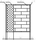 0
0
 Rreg
Rreg
R 0 =1/α int +R k +1/α ext R reg , where α int =8.7,α ext = 23
Dd = (t int -t ht) z ht = (20-(-3.3)) 207 = 4823.1
R reg = aDd +b = 0.00035x4823.1+1.4=3.088
1/8.7+Rk+1/23 3,088
Rk= 3.088-0.115-0.043=2.930
Rk= R 1 + R 2 + R 3 + R 4
R 3 = Rk – R 1 – R 2 – R 4 = 2.930-0.029-0.729-0.029 = 2.143
δ 3 =λ 3 xR 3 = 0.045x2.143 = 0.096 m.
We accept δ 3 =0.100 m, then R 0 f =3.090 (m 2 °C/W).
R 0 f > R reg
Table 4.1

We assume the thickness of the insulation in the outer wall is 100 mm, and the thickness of the wall itself is 650 mm (without the internal finishing layer).
Thermal engineering calculation of the enclosing structures of a warm attic. Attic floor
Required heat transfer resistance of a warm attic floor:
Ro gf =nRo reg,
where Ro reg is the standardized heat transfer resistance of the coating according to SNiP (Table 4).
n – coefficient determined by the formula:
n = (t int - t int g)/(t int - t ext),
where t int g is the design temperature in the attic, °C, established by calculating the heat balance for 9-story buildings at 15 °C.
Check the condition for the overlap:
where Δt = (t int - t int g)/(Ro gf α int).
Degree-day of the heating period:
Dd= (t int -t ht)z ht
where t int is the estimated internal air temperature;
t ht and z ht - average temperature and duration (days) of the period with average daily air temperature.
Standardized heat transfer resistance of the coating:
where a = 0.00045, b = 1.9 for a warm attic according to SNiP (Table 1b).
Heat transfer resistance:
R0 Rreg gf =1/α int +R k +1/α ext
where α int = 8.7 W/(m 2 °C) is the heat absorption coefficient of the inner surface of the attic floor (accepted according to SNiP, Table 4);
α ext = 12 W/(m 2 °C) - heat absorption coefficient of the outer surface of the attic floor for a warm attic (accepted according to SNiP, table 6);
Rreg gf = aDd +b = 0.00045x4823.1+1.9 = 4.070(m 2 °C/W)
n 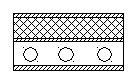 = (t int - t int g)/(t int - t ext) = (20-15)/(20+26) = 0.1087
Ro gf =0.4425(m 2 °C/W)
Δt = (t int - t int g)/(Ro gf α int) = (20-15)/0.4425x8.7 = 1.299< 3°С
R0 Rreg gf =1/α int +R k +1/α ext
Rk= 4.070-0.115-0.083 = 3.872
Rk= R 1 + R 2 + R 3 + R 4 + R 5
R 2 = Rk – R 1 – R 3 – R 4 - R 5 = 3.872-0.016-0.029-0.142-0.016 = 3.669 (m 2 °C/W).
δ 2 =λ 2 xR 2 = 0.046x3.669 = 0.169 m.
We take δ 2 =0.170 m.
Table 4.2

We assume the thickness of the attic floor insulation to be 170 mm.
1. Layout plan and relief organization plan…………………………………………..
2. Purpose of the building………………………………………………………………………………………………
3. Space-planning solution of the building…………………………………………………………………….
4. Specification of prefabricated reinforced concrete and concrete products……………………………………………..
5. Characteristics structural elements
5. 1 Foundations…………………………………………………………………………………..
5. 2. Walls………………………………………………………………………………..
5. 3. Thermal fur coat…………………………………………………………………………………..
5. 4. Coating slabs. Roof. Drainage…………………………………………………………….
5. 5. Floors…………………………………………………………………………………
5. 6. Partitions………………………………………………………………………...
5. 7. Windows. Doors. …………………………………………………………………………………..
5. 8. Stairs………………………………………………………………………………………………
5. 9. Exterior and interior decoration………………………………………………………
Bibliography…………………………………………..……………………………………
1. Layout plan and relief organization plan.
1.1. The shape of the described area is a rectangle with dimensions of 21.920 x 12.320 m.
The list of buildings and structures that are shown on the general plan is indicated on sheet AC-01.
1.2. The building is located in the northeast according to the location of facade 1-4.
1.3.Retraction surface waters is carried out through sewer inlet funnels located near the sidewalk on the road, for which the land leveling of the site should be done with a slope of i=0.01. The width of roads for single-lane traffic is 3.5 m, for two-lane traffic - 7 m. Roads have asphalt pavement with a minimum radius of curvature of 12m. The width of the sidewalks is 2.5 m, with a slope of 0.003%. The type of sidewalk covering is paving slabs.
1) Draw a layout plan (Figure 1)
|
1) We build a triangle of excesses (Figure 2)

2) Determine the slope i= 0.5/50 =0.01
3) Determine the absolute “black” marks of the corners of the building.
1st point 1: 217.0+19.5*0.01=217.195
2. point 2: 217.0+19.5*0.01=217.195
3. point 3: 217.5-17*0.01=217.33
4. point 4: 217.5-16*0.01=217.34
4) Determine the average “red” mark of the corners of the building.
(217,195+217,195+217,33+217,34+)/4=217,265
5) Determine the absolute mark corresponding to the relative mark 0.000
21,265+450=667,265
1.5. We determine the absolute “red” marks of the corners of the building, taking into account the slope = 0.003
1. point 4:
2. point 2:
3. point 1:
4. point 3:
5. point 2:
1.6. Snap two corners of a building to the axes of a geodetic grid
Angle 2. OA+4.5 OB+71
Angle 3. OA+4.5 OB+82
Angle 4. OA+25 OB+82
Angle 1. OA+25OB+71
1.7. Technical and economic indicators according to the general plan
a) the construction area of the entire territory is 10,000 m2.
b) building area 2270m2.
c) area open areas 2102 m 2
d) density –2270: 2102.
e) percentage of landscaping - 56.28%
f) green area - 5628m2.
2. Purpose of the building.
2.1. The building being designed is a 5-storey, 16-apartment rotating block section with an external corner.
2.2. The degree of fire resistance of the building is II - difficult to burn.
2.3. The degree of durability of the building is II - service life from 50 to 100 years.
2.4. Responsibility class – II.
3. Space-planning solution of the building.
3.1. The building's plan configuration is a rectangle with plan dimensions of 21,920 x 12,320 m
3.2. The building is frameless with load-bearing longitudinal and transverse walls. The pitch of the load-bearing walls is 6.3 and 5.4; 5.4 m. The building is 4-storey, floor height 3.0 m.
3.3. The spatial rigidity of the building is ensured by the following measures: as a result of the coupling of transverse and longitudinal walls with each other; anchoring covering and floor slabs to walls and to each other.
3.4. Main technical and economic indicators of the building:
1) Construction area – 270m2.
2) Construction volume – 3018 m 3 .
3) Total area – 270m2.
4. Specification of prefabricated reinforced concrete and concrete products.
| Pos. | (brand) | Designation | Name | Number | Unit weight kg |
| Note Plates | |||||
| strip foundations | B1.012.1-1.99 | ||||
| FL 10.24.3H | |||||
| FL 10.12.3H | |||||
| FL 10.8.3H | |||||
| FL 12.24.3H | |||||
| FL 12.12.3H | |||||
| FL 12.8.3H | |||||
| FL 8.24.3H | |||||
| FL 8.8.3H | |||||
| Concrete blocks for basement walls of buildings and structures | B1.016.1-181-98 | ||||
| FBS 24.5.6.N | |||||
| FBS 12.5.6.N | |||||
| FBS 9.5.6.N | |||||
| FBS 24.4.6.N | |||||
| FBS 12.4.6.N | |||||
| FBS 9.4.6.N | |||||
| Floor slabs | B1.041.1-2000 | ||||
| PK54.15-6 | |||||
| PK63.15-6 | |||||
| PK54.12-6 | |||||
| PK63.12-6 | |||||
| PK54.8-6 | |||||
| Stair elements | 1.251.1-4 | Lm1 | |||
| 1LMF25.13.14-4 | 1.252.1-4 | Lp1 | |||
| LPF28.11-5 | 1.252.1-4 | LP2 | |||
| LPF28.13-5 | |||||
| 1.238-1 | Visor |
5. KV18.28-T-2
5.1. Characteristics of structural elements.
Foundations.
Foundation type: solid, strip, prefabricated. It consists of foundation slabs adopted according to the B1.012.1-1.99 series (Figure 3). and concrete blocks adopted according to the B1.016.1-1.98 series (Figure 4) The layout of foundation slabs and blocks is shown in the graphic part of the project (sheet AS-02). The blocks are made of class B 7.5 concrete, slabs from class B 12.5 concrete. The main working reinforcement of the slabs is hot-rolled steel of periodic profile class A-I
II.
Sand preparation 150 mm thick is laid under the foundation. Under load-bearing walls A, B, D and D, foundation slabs with a width of 1200 are laid, and along axis B - 1400, and under the very load-bearing walls 1000. Placed under external walls concrete blocks
| 500 wide, and 400 for internal ones. | L | B |

H:
Legend
1. Insulated wall
2. PAROK insulation boards (RAL-4)
3. Adhesive composition SARMALEP
5. 4. Reinforcing mesh Plaster composition
SARMALITE
6. Dowel for strengthening insulation boards
7. Reinforcing corner 25x25 s
perforated mesh
Window and door openings in brick walls are covered with prefabricated reinforced concrete lintels. Jumpers are laid on brick walls by layer cement mortar
M 50.
| List of jumpers | Brand | List of jumpers | Brand | ||||||||||||||||
| Section diagram |
| PR-1 |
|
||||||||||||||||
| PR-6 | PR-2 | ||||||||||||||||||
| PR-7 | PR-3 | ||||||||||||||||||
| PR-8 | PR-4 | ||||||||||||||||||
| PR-9 | PR-5 |
PR-10
| Specification of jumper elements | Pos | Designations | Name | Col. per floor | Weight, kg. | ||||
| Note | |||||||||
| Total | B1.038.1-1 v.1 | ||||||||
| 2PB19-3 | |||||||||
| 5PB21-27 | |||||||||
| 2PB22-3 | |||||||||
| 5PB25-27 | |||||||||
| 1PB10-1 | |||||||||
| 3PB16-37 | |||||||||
| 2PB13-1 | |||||||||
| 2PB25-3 | |||||||||
| 5PB27-27 |
5.4. 3PB13-37
Coating slabs. Roof. Drainage The ceilings are made of prefabricated with round voids 220 mm thick. The range of plates is given in the catalogue. Designed according to the B1.041.1-1.2000 series. The slabs are reinforced with prestressed ordinary and wire reinforcement. Cover slabs are similar to floor slabs. Roof slope 2.5%.
The slabs are supported on load-bearing walls with short sides along the layer cement-sand mortar, minimum support depth 120 mm.
The voids at the ends of the slabs are sealed with concrete to a depth of support, but not less than 120 mm. This protects the ends of the slabs from being pushed through by the overlying wall, and also improves the heat and sound insulation properties of the floor.
The joints between the slabs are filled with class B15 concrete in small fractions.
The layout of the coating slabs is located in the graphic part of the project (sheet AS-02)
The drainage system in the building is internal through 2 water intake funnels installed in the hole of the roof slab.
The roof plan is located in the graphic part of the project (sheet AS-02). The composition of the roof is shown on node 1 shown in the graphic part of the project (sheet AC-01).
5.5. Floors.
The designed building adopted following types floors
Explication of floors.
| Room number | Floor type | Floor diagram | Floor element data (name, thickness, base) | Floor area, m2. |
| Bathrooms, corridors |
 | 1. Ceramic tiles for floors GOST 6787-90 according to the project - 13 mm 2. Glue "Polymix K" STB 1072-97 - 7 mm 3. Strengthening polymer primer STB 1263-2001 4. Self-leveling screed -10 mm 5. Waterproofing "Polymix" GS" STB 1072-97 – 3 mm 6. Polymer primer – 2 mm 7. Light expanded clay mortar – 40 mm 8. Strengthening polymer primer 9. Reinforced concrete hollow-core slab | ||
| Bedrooms |
 | 1. Piece parquet GOST 862.1-85 2. Adhesive composition – 2 mm 3. Strengthening polymer primer STB 1263-2001 4. Self-leveling screed STB 1307-202 – 10 mm 5. Polymer primer STB 1263-2001 – 1.5 mm 6. Light expanded clay mortar STB 1307-2002 – 40 mm 7. Strengthening polymer primer STB 1263-2001 8. Reinforced concrete hollow-core slab |
5.6Partitions.
The partitions are made of brick, 120 mm thick. Partitions are made from solid brick grade KPO – 125/35/STB 1160-99, on cement-sand mortar M75 with plasticizing additives. For connections between partitions and ceilings, see AS-02.
When laying, the horizontal and vertical joints are completely filled. The laying is carried out using a chain system.
The openings in the partitions are covered with prefabricated reinforced concrete lintels. The jumpers are designed according to the B1.038.1-1.1 series. The lintels rest on the walls over a layer of M50 cement-sand mortar.
5.7.Window. Doors.
The windows are designed according to the STB 939-93 series with triple glazing: with double-glazed windows and glass from the inside with separate paired sashes, and with double glazing: double-leaf.
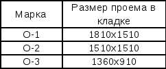
There are only three types of windows.
List of openings
Specification of opening filling elements
| Pos. | Designation | Designations | Col. along the facades | Weight, kg. | Weight, kg. | ||||||||
| 1-4 | A-B | 4-1 | B-A | Total | |||||||||
| Door blocks | |||||||||||||
| 1.138-98 | DNDG24-15Shch | ¾ | ¾ | ¾ | |||||||||
| DVDG21-10SHL | ¾ | ¾ | ¾ | ¾ | |||||||||
| DVDG21-8SHL | ¾ | ¾ | ¾ | ¾ | |||||||||
| DVDG21-6SHL | ¾ | ¾ | ¾ | ¾ | |||||||||
| DVDG21-15Shch | ¾ | ¾ | ¾ | ¾ | |||||||||
| DVDG21-10Shch | ¾ | ¾ | |||||||||||
| DVDG21-8Shch | ¾ | ¾ | ¾ | ¾ | |||||||||
| DVDG21-6Shch | ¾ | ¾ | ¾ | ¾ | |||||||||
| DVDG21-12Shch | ¾ | ¾ | ¾ | ¾ | |||||||||
| Window blocks | |||||||||||||
| OK-1 | 939-93 | O3S12-15SSP | ¾ | ¾ | ¾ | ||||||||
| OK-2 | O3S18-15SSP | ¾ | |||||||||||
5.8. Stairs.
The building is designed flights of stairs, resting on landings, and landings resting on the walls of the building. The stairs are selected according to series 1.252.1-4.issue 1.
Stairs and landings lined with a layer of cement mortar with marble chips 15mm thick.
5.9. External and internal finishing.
The facades are plastered and painted with facade paint.
Inner surface The walls are plastered, respectively, the masonry is carried out, leaving the front seams unfilled to a depth of 10-15 mm to ensure good connection of the plaster layer with the wall. The inner surface is painted with oil paint.
In restrooms, in the areas where sanitary and technical fixtures meet, glazed tiles are lined to a height of 1.8 m, the rest of the surface is painted with enamel to a height of 1.8 m.
Bibliography.
Buga P. G. “Civil, industrial and agricultural buildings” Moscow 1987
Nilov V. A. “Civil buildings” Moscow 1988
Maklakova T. G. et al. “Structures of civil buildings” Moscow 1986
Sherezhevsky I. A. “Design in civil buildings” Leningrad 1981
Gnevoy A.F., Usik S.A. “Course and diploma design” Leningrad 1987
“Rules for the implementation of working documentation for master plans of enterprises, structures and housing and civil facilities.” GOST 21.508-93 SPDS
"Basic requirements for working documentation." GOST 21.101-93 SPDS
“Rules for the execution of working documentation” GOST 21.501-93
"Windows and balcony doors for buildings and structures" STB 939-93
“Territorial catalog of industrial structures and products for housing and civil construction in the Belarusian SSR. Collection TK2-03.00.91 in three volumes"
“Territorial catalog of industrial structures and products for industrial construction in the BSSR. Collection TK2-01.00.93"
Explication of floors Calculation and design section2.1. Determination of structure dimensions and design characteristics of materials
We make calculations according to the first group limit states. Slab size (nominal) 4000x1200x220 mm. Materials concrete B25; class A-II reinforcement (Rs=280 mPa, Rsw=225 mPa); transverse reinforcement made of steel class A-I (Rs=225 mPa, Rsw=180 mPa).
Temporary payload 200 kgf/m2, including 70 kgf/m2 – long-term and 130 kgf/m2 – short-term.
Calculation:
1. The structural length of the slab is equal to the distance between the centers of the supports:
Lк = L – b w = 4000 – 20 = 3980 mm,
Where 20 mm is the width of the seam between the plates.
2. Design width of the slab:
H 0 = H – W = 1200 – 20 = 1180 mm,
Where 20 mm is the width of the seam between the tiles.
3. Round voids with a diameter of 159 mm, the smallest distance between which is 30 mm. Then the required number of voids in the slab:
N= 1180 = 6.24=6 pcs
4. Width of extreme ribs:
= [(V k – n × d – b 1 × (n – 1)] / 2 = [(1180 – 6 × 159 – 5 × 30)]/ 2 = 38mm
5. Distance from voids to the outer surface of the slab
h ƒ = (h – d) / 2 = (220 – 159) / 2 = 30.5 mm
6. We accept the design section as a T-section with height h = 22 cm, thickness h ƒ = 30.5 mm.
7. Width top shelf brands
b = B to – 2 × 15 = 1180 – 30 = 1150mm (15 mm is the size of the side trims)
8. Rib width:
b p = b ƒ –d × n = 1150 – 6 × 159 = 196mm = 19.6cm
9. Working section height:
h 0 = h – a = 220 – 30 = 190mm = 19 cm
10. Design span of the slab L 0 = 3980 – (190+180)/2 = 3795 mm = 3.8 m
Collection of loads on 1 m 2 floor coveringsNote: we use the density of materials according to the density table.
The load per 1 m2 of slab length is collected from its nominal width
(b n =1.2m) g=g n *b n = 6.79x1.2=8.15 kg/m


