Electrical circuit of an air conditioner fan. Air conditioner connection. Features and requirements. Video instruction "Installing an air conditioner from LG"
And where does the refreshing coolness come from on a hot summer day? It is necessary to consider in detail the main principles of air conditioning systems. To do this, it is worth recalling school physics lessons, which dealt with the absorption of heat by a liquid, and a simple experiment: cologne or alcohol was poured onto your hand, which in the process created a pleasant chill. It is this simple principle that is used in modern air conditioners.
What does a standard split system consist of? As a rule, inside it there is a closed circuit along which the liquid moves -. Flowing inside the circuit, the refrigerant absorbs heat in one place in order to release it in another. This process takes place in special tubes - which are made of copper and contain transverse partitions made of aluminum. To speed up processes, air is pumped into the heat exchangers using special fans.
Based on the name of the processes occurring in the heat exchanger, one of them is usually called, and the other -. When the air conditioner operates “heat” it acts as internal evaporator(the part of the air conditioner located in the room), and when operating “in the cold”, everything happens the other way around. That's how operating principle of air conditioner, but what's the point?
Cold itself is not a complete product, but only a derivative of the transfer of heat using a refrigerant. This process is called "" in the literature. Thanks to it, the performance of the air conditioner is three times higher than its energy consumption. At first glance, this may cause bewilderment: efficiency is 300% - is this really possible? What is refrigerant and how can it be transferred from a room where the temperature is about 20 degrees to outside where the temperature is twice as high?
It turns out that everything is much simpler than one might imagine. Temperature transfer directly depends on pressure, and it occurs not linearly, but monotonically. Thus, during transportation, the pressure value becomes higher than the phase transition temperature. The boiled refrigerant changes its state from liquid to vapor and begins to absorb heat from the surrounding air, while the necessary pressure is created in the heat exchanger, at which the phase transition temperature becomes lower than the ambient temperature. In the reverse process, the refrigerant releases its heat to the air and the junction temperature rises.
One more important detail in the operation of the air conditioner is closed loop, to create which you need at least two elements: - to increase the pressure and a throttling device - to lower it. The first of them is installed directly in front of the capacitor, and the second in front of.
In general, there are five elements that are required in any type of air conditioner: a closed circuit, an external and internal heat exchanger, a compressor and a throttling device. They are the main component of both the simplest and the most complex split systems.
Nowadays, for full-functional operation of the air conditioner, they add four way valve, thanks to which it can produce both heat and cold. This split system is called " reverse cycle air conditioner», additional function which was the transfer of heat from the room to the street and back.

- 3. Compressor- compresses freon and maintains its movement along the refrigeration circuit. The compressor is of piston or scroll type. Piston compressors cheaper, but less reliable than spiral ones, especially in conditions low temperatures outside air.
- 5. Four way valve- installed in reversible (heat - cold) air conditioners. In heating mode, this valve changes the direction of movement of freon. At the same time, internal and outdoor unit seem to change places: indoor unit works for heating, and the outside one works for cooling.
- 4. Control board- as a rule, it is installed only on inverter air conditioners. In non-inverter models, they try to place all electronics in the indoor unit, since
- Large changes in temperature and humidity reduce the reliability of electronic components.
- 1. Fan- creates a flow of air blowing over the condenser.
- In inexpensive models, it has only one rotation speed.
- Such an air conditioner can operate stably in a small range of outdoor temperatures. In higher-class models designed for a wide temperature range, as well as in all semi-industrial air conditioners, the fan has 2 - 3 fixed rotation speeds or smooth adjustment.
- 2. Capacitor- a radiator in which freon is cooled and condensed. The air blown through the condenser is correspondingly heated.
- 7. Freon system filter- installed in front of the compressor inlet and protects it from copper chips and other fine particles which may enter the system during installation of the air conditioner. Of course, if the installation was carried out in violation of the technology and a large amount of debris got into the system, then the filter will not help.
- 6. Union connections- copper pipes connecting the outdoor and indoor units are connected to them.
- 8. Protective quick release cover- covers the fitting connections and terminal block used to connect electrical cables. In some models, the protective cover covers only the terminal block, and the fitting connections remain outside.
Air conditioner indoor unit

- 1. Front panel- is a plastic grill through which air enters the unit. The panel can be easily removed for servicing the air conditioner (cleaning filters, etc.)
- 2. Filter rough cleaning - is a plastic mesh and is designed to retain coarse dust, animal hair, etc. For normal operation of the air conditioner, the filter must be cleaned at least twice a month.
- 5. Evaporator- a radiator in which cold freon is heated and evaporated. The air blown through the radiator is cooled accordingly.
- 6. Horizontal blinds - regulate the direction of the air flow vertically. These blinds are electrically driven and their position can be adjusted from the remote control. remote control. In addition, the blinds can automatically perform oscillatory movements to evenly distribute air flow throughout the room.
- 7. Display panel- indicators (LEDs) are installed on the front panel of the air conditioner, showing the operating mode of the air conditioner and signaling possible malfunctions.
- 3. Fine filter- It happens various types: charcoal (removes unpleasant
- odors), electrostatic (retains fine dust), etc. The presence or absence of fine filters does not have any effect on the operation of the air conditioner.
- 4. Fan- has 3 - 4 rotation speeds.
- 8. Vertical blinds - serve to adjust the direction of the air flow horizontally. In domestic air conditioners, the position of these blinds can only be adjusted manually. The ability to adjust from the remote control is only available in some premium air conditioner models.
- Condensate tray(not shown in the figure) - located under the evaporator and serves to collect condensate (water formed on the surface of the cold evaporator). From the pan, water is discharged outside through a drainage hose.
- Control board
- (not shown in the figure) - usually located with right side indoor unit. This board contains an electronics unit with a central microprocessor.
- Union connections
- (not shown in the figure) -
- located at the lower rear of the indoor unit. Copper pipes connecting the outdoor and indoor units are connected to them.
Operating principle of the air conditioner
Any air conditioner consists of two parts with different functions: a refrigeration circuit, which performs the function of air cooling and electrical part, which controls devices and circuit elements.
This article will look at the electrical circuit of the air conditioner, options for connecting it to the power supply, and how to properly connect the air conditioner to the power supply.
What is the electrical diagram of a split system
Electrical diagram air conditioner is a document that displays the location of electronic components, their connections, as well as information for engineers service centers. Anyone who is interested is more interested in the electrical wiring diagram for the air conditioner, which includes the location of the main evaporative and capacitor unit, terminals for connecting the blocks to each other and connecting the power supply.
The main elements here are:
- Compressor, with CSR terminals. The arrow shows the protection installed on the compressor winding
- Compressorcapacitor - a capacitor with two terminals connected to the windings of the compressor unit. The third terminal of the capacitor is connected to its starting winding.
- In addition, the diagram shows a fan motor and a capacitor through which two windings of the electric motor are connected.
- The diagram shows an electromagnet that controls the operation of a four-way valve.
Terminal designations in the terminal block:
1(N) – zero.
3 – Supply power to the fan motor when operating at low speeds.
4 – Power supply to the fan motor when it operates at high speeds.
A separate terminal is ground.  Main modules and blocks:
- Power filter through which voltage is supplied to the control board.
- Control board – control unit to which all device modules are connected.
- A compressor power relay is connected to CN 12.
- A drain pump is connected to CN6.
- Terminal block CN 5 is responsible for controlling the fan of the split system.
- A stepper motor for controlling the blinds is connected to the CN 10 pins.
- CN 7 terminals are responsible for connecting the heat exchanger temperature sensor.
- A room temperature sensor is connected to pins 1 and 2 of terminal block CN15.
- A water level sensor in the pan is connected to pins 1 and 3 of terminal block CN15.
- Terminal block CN 13 of the control unit is responsible for connecting the device display unit.
Terminal block (labeled Terminal on the board) for connecting the evaporative and condenser units with a cable. Terminals L and N - power supply of the air conditioner from the electric line. transmission You should know that there is an option to connect the air conditioner to the mains via an external unit.
With this connection, you must follow the instructions. If climate control equipment with a power of up to 4.5 kW is connected, then a four-core copper cable with a cross-section of 2.5 mm 2 must be used. With a separate power supply branch, a 20 A circuit breaker must be installed on the panel. 
Air conditioner connection
Afterwards they must be connected to each other with a four-wire copper cable with a core cross-sectional area of at least 2.5 mm 2. Connection instructions are circuit diagram, which was discussed in some detail above. The connecting cable can be laid together with the freon line, or maybe in a separate plastic box.
When laid in one groove together with copper tubes, use corrugated plastic tube to insulate the cable.
After the inter-unit electrical connection, the indoor unit should be connected to the power supply. The connection diagram for the air conditioner to the electrical network involves receiving power both from the nearest outlet and from a separate line.
The ideal connection option is a sufficiently powerful climate control technology is a separate power line. This option will not load the existing lines of the apartment electrical system and will allow power to be supplied directly to the internal unit of the split system. The power supply cable can be laid from the panel to the indoor unit using a groove in the wall material or in a special plastic box. 
The shield from which the separate power line will be drawn must be grounded. The connection of the power cable to the terminal block of the panel must be carried out only through an automatic machine, the power of which should be calculated using the formula: the power of the device divided by the voltage. 30% of the reserve should be added to the resulting value.
It should be understood that the power cable for air conditioning equipment can be connected to the outlet only if:
- Climate control equipment has low power.
- The in-house electrical network is laid with a copper cable with a cross-section of at least 2.5 mm 2.
- There are no energy-intensive consumers on the same branch with the air conditioner.
- Supposed to be temporary.
- This power supply branch is equipped with a circuit breaker with an RCD of at least 20 A.
Options for connecting an air conditioner to an existing power line
This issue could not be considered, due to the presence of sockets in the room. But, some owners of low-power climate control equipment are dissatisfied with the stretching wire from the outlet to the consumer, often across the entire wall.
If the outlet is located far enough from the air conditioner, then there is an option to connect the air conditioner to the mains via a switch. We warn you right away: this option is only suitable for low-power climate control equipment and here’s why: the terminals of a conventional switch may simply not withstand the current passing through them. The result is heating, sparking, failure of the switch (at best) or fire. 
It is better to cut a groove in the wall from an existing outlet and lay a power cable along it in a corrugated pipe to the split system unit, and then install a special outlet with a decorative cover into the wall. The socket must withstand a certain current: if the power is 1 kW, then the socket must withstand 9-10 A; from 1 to 3 kW – 16-18 A; from 3 to 4.6 kW – 20 A; from 4.6 to 5.5 – at least 25 A. Right choice It is best left to a qualified electrician.
If you decide to connect the air conditioner yourself, then do it in compliance with all safety regulations, and in order to be completely sure that the connection process was completed correctly and safely for the climate control equipment and the inhabitants of the home, it is best to seek help from professionals.
So your dream has come true - an air conditioner has appeared in the house, now the heat in the summer period and dampness in the room in the off-season, when the heating has not yet been turned on, and there are prolonged rains outside the window. Immediately after installation, the air conditioner is connected to the electrical network - it must be carried out strictly according to the diagrams indicated on the internal covers of the modules. The operating instructions also contain recommendations for making connections and specify the basic requirements for electrical network installation locations.
It must be remembered that the electrical connection diagram for an air conditioner used in everyday life differs significantly from the similar connection of semi-industrial models that are installed in offices. Pets only have single-phase connection.
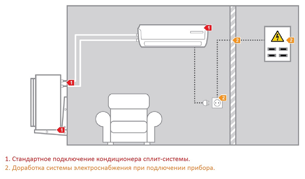
In practice, there are two main ways to connect a split system:
- direct connection via socket;
- separate wiring to the electrical panel.
The first option is ideal for all household devices - they are everywhere put into operation only in this way. Connecting any air conditioning system is carried out in several steps, which must be strictly followed when you decide to do everything yourself.
Connection diagram of the air conditioner to the electrical network
The figure shows a diagram of connecting the air conditioner to the electrical network, as well as various connections between the system modules; in addition, you will definitely need a circuit diagram of the air conditioner of the purchased model.
First way
Before you begin connecting the product to the network, you must install cables from the evaporator to the outdoor module:
- we lay the wire that will connect the two blocks;
- we draw a separate line to the electrical panel for powerful systems, which includes a cable and an overload protection circuit breaker;
- Medium power devices are connected directly through an ordinary outlet.
The last option for connecting an air conditioner is used in certain cases:
- the power of the product is low;
- window or mobile class climate system;
- the apartment has a network of sufficient power;
- temporary location of the unit;
- Others must not be connected to this line. Appliances.
Important! To connect the indoor unit, you need to use reinforced sockets and install a circuit breaker nearby.
It must be taken into account that the air conditioner operates in different modes, its power varies from minimum to maximum, so separate protection must be installed on the connection line.
Before sending a product for sale, each manufacturer attaches instructions to it, which include:
- product operation diagram;
- connection diagram - general;
- electrical diagram for connecting the external and internal units.
There is similar information on the surface of the remote unit housing and the evaporator cover, but it is applied from the inside. This greatly simplifies the independent connection of any air conditioning system at home.
Under the front panel of the evaporator there is a special box where the terminals for connecting wiring- this air conditioner unit or split system is always installed indoors.


The wires from the evaporator are connected to the contacts of the outdoor unit, guided by the numbering; the free wires are carefully insulated with special tape. The schematic diagram will help you understand everything correctly. Before connecting the air conditioning system, you must check insulation of each core so that the normal operation of the air conditioner is not interrupted by a short circuit.
Important! If the system diagram is unclear to you and you have no practice in working with electricity, then it is better not to try to connect the split system yourself, but call a professional.
There are reasons that do not allow connecting any air conditioning system to the electrical network of an apartment or country house:
- old wiring where aluminum wire was used;
- the cross-section of the wires is too small - they will not withstand the load;
- the condition of the wiring requires its urgent replacement;
- There is no high-quality grounding or basic protection against voltage surges.
Air conditioning systems are rather delicate devices, so they should only be connected to working electrical network so as not to waste family budget for very expensive repairs.
Second way
Experts advise using the most reliable and safe option connecting the air conditioner - an individual cable that ensures stable operation of the device.
If you install separate protection - an RCD (residual current device), it will protect the product from any voltage drop or network overload, and an individual line will allow you to place system modules anywhere.
- Standard requirements for the components of a separate electrical line: Necessarily presence of RCD or AZO
- (residual circuit breaker);
- all conductors must be made of copper;
- the diameter of the wire must correspond to the size prescribed by the manufacturer; equip separate grounding
Electrical harnesses are passed into a protective hose, then placed in a specially designed plastic box so as not to violate the integrity of the walls. Watch how the professionals make the connection in this special video:
Work algorithm
When House master If he is confident in his abilities and knows perfectly well how to connect various household appliances, he can safely start working according to a fairly simple scheme.
- Selecting a set the necessary tool and the necessary materials.
- We study the schemes proposed by the manufacturer.
- We lay the cables to connect the terminals external unit to similar connectors of the air conditioner evaporator.
- We check the proper operation of all components of the product.
It does not depend on the design of the product where the cable for connecting to the outlet comes from - from the evaporator or the external module.
Choosing an outlet
A home outlet must meet certain requirements:
- Availability is welcome differentiated relay or reliable grounding;
- it must fully meet all the requirements and parameters drawn up by the manufacturers, according to the appendices in the instructions for using the split system;
- if the socket is supplied with electricity using aluminum wires, it must be replaced with copper analogues with a normal cross-section;
- it must be connected to the panel via a circuit breaker.
Modern standard euro sockets perfect for connection household appliances special power, but all work on connecting the air conditioner must be performed by a specialist with the appropriate approval, otherwise the product warranty will be void. If you moved to a new place and decided to install a product that was already working, especially since you carried out the dismantling yourself, then follow the recommendations and do everything carefully.
Selecting the wire
To correctly connect the air conditioner with your own hands, you must use a wire only of the cross-section specified by the manufacturer individually for each model.
Household products require the use of a cross-section within the range of 1.5-2.5 square (mm 2), and the current strength will correspondingly be up to 18 amperes or more.
If the distance between the system and the electrical panel is up to 10 m, then a cross-section of 1.5 mm 2 is suitable, when the distance is greater, then the cross-section increases. For efficient work climate systems use copper wires


: for single-phase connection - 3 wires, for three-phase version - 5 wires. Wires are not laid near pipes and gas supply, the standard distance between communications is no closer than a meter. Electrical harnesses, assembled in a protective corrugation, are placed in grooves and secured with special clamps.
When laying communications using ducts, glue and screws are used to secure the wiring. When they do hidden wiring , then the cables are secured in the grooves with special clamps, and then plastered with construction plaster so that they can be quickly opened in case of emergency.
Connecting the evaporator
In principle, the method of connecting system modules is identical, with the exception of minor nuances, so we present detailed methodology connection of the internal module, and the external one - by analogy with it.

After completing the connection of both modules, check again correct connection, checking the diagrams, only after a scrupulous check is a trial and short-term switching on of the air conditioner performed.
In conclusion, I would like to warn all users once again: electricity does not forgive mistakes and inaccuracies, so when self-connection use your skills adequately so that you don’t have to deal with extinguishing wiring and repairing expensive climate control equipment later.
When buying a room air conditioner, it is very important to choose the right one technical characteristics and handle the installation responsibly. According to statistics, the majority of air conditioner breakdowns occur due to their incorrect and unskilled installation. Correct sequence Connecting the electrical circuit of the air conditioner is the key to its high-quality and long-term performance. If the air conditioner is installed incorrectly, the following negative characteristics may subsequently appear: condensation leaking into the room, freon leakage, etc.
There are two types of installation of air conditioners in premises: standard and non-standard. Standard installation is the most common, installing the air conditioner near a window, since the compressor is located outside. It is possible to perform installation in rooms that have been renovated. This installation is not expensive and does not take much time.
Custom installation Air conditioning is quite an expensive and painstaking job, which is recommended to be done only during the renovation of the room, since it involves chipping the walls.
Regardless of which installation option you choose, to avoid all negative consequences, before starting installation of the air conditioner and mountings, it is worth finding out important points. For example, such as external connection diagram and electrical diagram, electrical supply system of the device, location of input devices, cross section wires and future cable routes, find out the characteristics of the walls involved in the electrical wiring route. The electrical circuit of the air conditioner must comply with the rules for electrical installations and regulatory documents. Participation is important professional team specialists with the necessary equipment.
Air conditioner connection diagram
The electrical connection diagram for the air conditioner includes the laying of external wiring, secured every 50 cm with special clamps. Electrical wiring placed in boxes is attached to the wall using glue and screws, and hidden electrical wiring is located in recesses in the wall in corrugated pipes, attached with clamps.
When choosing a place to install an air conditioner, first of all you need to take care of the aesthetic characteristics: design and interior. It is recommended to install the air conditioner in the ceiling area in a place where you do not spend a lot of time, as direct flows of cold air can lead to colds.
Refrigeration circuit diagram
Below is a diagram refrigeration circuit air conditioner
The diagram was taken not from a textbook, but from the manufacturer’s service documentation, therefore the designations are given in English.

Compressor- compressor, the “heart of the air conditioner”. The compressor compresses the refrigerant and pumps it through the circuit.
Heat exchanger- heat exchanger,
- outdoor unit- the external unit, that is, the condenser, cools the compressed freon below the condensation temperature
- indoor unit- indoor unit - evaporator, in which the working substance evaporates, lowering the temperature
Expansion valve- expansion valve
In other words, TRV is a thermostatic valve. Provides feed required quantity refrigerant.
IN simple air conditioners its role is performed by a capillary tube, without any adjustment; in inverter systems - an electronic expansion valve.
2-Way valve- two-way valve, that is, a regular valve, with two positions - open and closed
3-Way valve - three-way valve, in an air conditioner, this is the service port to which the pressure gauge hose is connected for measuring pressure or charging.
4-Way valve- four-way valve, provides refrigerant reverse for operation of the air conditioner in heating mode
Strainer- filter, in this diagram it is a filter-drier, since it is installed before the expansion valve (and after, since the system can operate in reverse mode and the refrigerant changes direction of movement).
Its task is to prevent moisture from entering the thin channel of the expansion valve - since moisture will clog it, preventing the refrigerant from passing through.
Muffler- muffler
The arrows indicate the direction of movement of freon along the contour:
- solid arrow - in cooling mode
- dotted arrow - in heating mode
Also in more complex and advanced air conditioners the following is installed:
- Pressure Sensors
- liquid separators
- bypass lines
- injection systems into the compressor
- oil separators
Multi split system diagram
Multi split system- this is an air conditioner that has one external unit and several internal ones

In this case, several more internal blocks are added, as well as:
Distributor- a distributor that splits the refrigerant flow and directs it to several indoor units.
The diagram also contains elements that are used not only in multi-systems:
Receiver tank - receiver.
The receiver has several purposes - protection against compressor water hammer, draining freon during repairs, etc.
In this case, it is a linear receiver that prevents freon gas from entering the expansion valve
Scheme electrical connections external unit of split system:

Terminal - terminal block for connecting an interconnect cable for connection with the indoor unit.
N- electric neutral
2 - supplying power to the compressor from the control board of the indoor unit
3 - supplying power to the fan motor for operation at 1st speed
4 -
supplying power to the fan motor to operate at 2nd speed
5 - drive power supply four way valve to switch to heating mode
Compressor
C- common - common output of the compressor windings
R- running - compressor working winding
S- starting - phase-shifting winding of the compressor motor, starting
Internal overload protector- internal overload protection
Compressor Capacity- an electric capacitor, in this case a working one (there are also starting ones, but they are not currently used in air conditioners)
Fan motor- engine, fan motor
Thermal protector- protection against overheating, usually placed directly on the motor windings and breaks the circuit when the temperature is exceeded.
Fan motor Capacitior - fan motor run capacitor
SV- solenoid valve - solenoid valve, driving the four-way valve mechanism.
Air conditioner indoor unit diagram
Terminal block
On the terminal block, in addition to interblock connections, there are also clamps for connecting power (power can be supplied vice versa - to the external unit)
L, N- electric line and neutral of single-phase power supply
Filter Board - filter board, reduces the level of interference in the power supply network
Control Board - control board - controls all devices, receives data from all sensors, performs thermoregulation, displays information for the user, and performs self-diagnosis.

Main relay- main relay - a power relay that supplies voltage to the compressor.
Display board - The display module can be a line of LEDs that indicate the presence of power, the selected mode, an error code, or a display that also displays the temperature.
Thermistor - thermistor, thermistor, temperature sensor
Room temp. - room temperature sensor
Pipe temp. - temperature sensor of the heat exchanger tube, evaporator
Temperature sensors may also be located in:
- control panel - to maintain the temperature at the location of the remote control (for example, “I Feel” mode).
- at the inlet, outlet and midpoint of the evaporator
Step motor - stepper motor,
Used to open louver grilles or curtains covering a fan
Despite the fact that there are air conditioners in almost every home, only a few users correctly imagine the circuit diagram of such a device and how it works and is connected. In this article we will try to cover this topic in detail.
General diagram of the air conditioner operation
The entire system is built on the ability of substances to absorb heat during evaporation and release it during condensation. This air conditioner circuit is incorporated into the operation of a modern split system. The main substance inside closed system device is freon. Having the ability to change its state of aggregation by changing temperature and pressure, we will be able to cool the radiator and drive air from the street through it.
But first, let's get acquainted with the basic elements of a split system. The circuit and principle of operation of the air conditioner involve the use of two units: external and internal. What are they needed for?
Outdoor unit
This unit is installed outdoors and mainly serves to cool overheated freon (it does not take air from the street, the air conditioner is used to cool the air in the room. Ventilation units are used to take in outside air). It consists of the following nodes:
- Fan.
- Capacitor. In this part, freon is cooled and condensed. The air that passes through the condenser is heated and discharged to the street.
- Compressor. Main element an air conditioner that compresses freon and ensures its circulation throughout the entire circuit.
- Control block. It is commonly used in outdoor units of inverter systems. In conventional air conditioners, all electronics are most often located in the indoor unit.

- 4-way valve. Used in models that can operate for heating (most modern air conditioners). This element, when the heating function is activated, changes the direction of movement of the refrigerant. As a result, the outdoor and indoor units change places: the indoor unit works for heating, the outdoor unit for cooling.
- Various fitting connections through which the connection occurs copper pipes between indoor and outdoor units.
- Refrigerant filter. It is installed in front of the compressor in order to protect the latter from dirt that may enter the system during installation.
Indoor unit
It includes elements:
- The front panel through which air enters. It can be easily removed so that the user can get to the filters.
- The coarse filter is a normal plastic mesh, which traps large dust (for example, animal hair, fluff, etc.). This mesh needs to be cleaned once a month.
- Filter system consisting of carbon, antibacterial, electrostatic filters. Depending on the air conditioner model, some filters may not be present at all.

- Fan for circulation clean air indoors - cold or heated.
- Evaporator. It is a radiator where the ice coolant enters. This radiator is heavily cooled by freon, and the fan drives air through it, which instantly becomes cold.
- Blinds for adjusting the direction of air flow.
- The indicator panel shows in which mode the air conditioner is operating.
- Control board. It houses the central processor and electronics unit.
- Union connections - pipes connecting the indoor and outdoor units are connected to them.
The air conditioner circuit is simple and logical, but some users do not understand why two units are needed? After all, you can take warm air from the room and run it through the air conditioner, cooling it. But it's not so simple: you can't produce cold without producing heat. And the heat needs to be removed outside. A two-block system is ideal for this purpose. There are also other systems, such as single-block ones. There, the heat is removed outside through a special air duct taken outside the apartment.
Detailed diagram of the air conditioner operation
Now that you know the basic elements, you can consider in more detail how this system works. So, when the cooling mode is activated from the control panel, the compressor in the system turns on. It builds up pressure and forces gas through the radiator. After passing through the radiator (in the outdoor unit), the gas becomes liquid and hot (if you remember, when it condenses, it releases heat).

Now the hot liquid freon (which was a gas before the radiator) enters where the freon pressure decreases. As a result of this, freon evaporates, and a cold gas-liquid mixture enters the evaporator (freon becomes cold when evaporating). The evaporator cools down and the fan blows the cold from it into the room. The freon gas then enters the condenser again, and at this point the circle is completed.
This air conditioner circuit diagram is valid for all types. Regardless of the model, power and functionality of the system, all air conditioners are built exactly according to this principle, including automotive, industrial and household ones.
Air conditioner connection
The air conditioner installation diagram is simple, but the installation itself is quite complex. It can only be done by specialists who have the appropriate equipment. The whole difficulty lies in installing the outdoor unit and pumping freon inside. It is also necessary to make a huge hole in the wall, and if the house is panel, the complexity of the work increases.

As for connecting to the electrical network, it is enough to simply connect the internal unit of the device to an outlet, nothing more. But the power supply connection diagram for the air conditioner is a document that shows the location various components and information for service centers. It is of greater interest to engineers who repair and connect equipment. In the context of this article, it is impossible to provide a single diagram for connecting an air conditioner, since it is for various models may be different.
Connecting blocks
After the external and internal air conditioner units have been installed, they must be connected to each other. This is done using a copper four-core cable. The cores must have a cross-section of at least 2.5 mm 2. The air conditioner connection diagram that comes with the device itself is, to some extent, an instruction manual. Usually the connecting cable is laid together with the freon line, although it can also be laid in a separate plastic box.
Connection via leased line
After connecting the two units to each other, you need to connect the indoor unit to the network. You can use the nearest outlet, however, given the fairly high power installation, experts recommend providing a separate power line for it, which will go directly to the meter. This will remove a large load from the common line of the apartment's electrical system. The cable can be laid to the shield using a special groove or in a plastic box. Do not leave the wire exposed.

The panel into which the air conditioner power line (and the general line of the apartment's electrical system) will enter must be grounded. In this case, the cable power must be connected through a circuit breaker of a certain power. It is calculated using a special formula: air conditioner power divided by voltage (220 or 230 V). To the obtained value you need to add 30% for power reserve.
Connection to the apartment's general power supply system
Connecting the device to a regular outlet that belongs to a common power line is only possible if your air conditioner is not powerful and will not create a large load on the network. If the power consumption of the air conditioner is 1 kW or less, it can be connected to a regular outlet. Typically, models designed to cool 20 square meters have this power.


