Images - views, sections, sections. Selecting images and planning a sketch or drawing What product is called an assembly unit
28.1. Selecting the main image in the drawing. When constructing drawings, it is important to select the number of images that allows you to obtain sufficient information about the product. At the same time, one should strive to the smallest number images giving necessary characteristics the depicted object.
The number of images in the drawing depends on the complexity of the structural form of the object. Often, to provide a complete picture of the shape of a part, one image is enough - a view or a section using established signs and inscriptions (for example, signs of diameter, square, indicating the thickness and length of the part, etc.). Examples of such images were given in textbook previously.
To identify the shape of a part in a drawing great importance has the correct main image selection. Such an image can be a view, a section, or a combination of both.
The main image should give the most complete idea of the shape of the part, the shape of its parts and their sizes, i.e. the most complete information. From the right choice The number of images in the drawing also depends on the main image. For this purpose, they try to position the object relative to the projection planes so that most of its elements in the main view are depicted as visible.
Typically, the drawing shows the part in the position it occupies during processing. So, for example, the axis of parts produced by turning on a machine is placed horizontally in the drawing (bushings, shafts and other parts).
- Remember which image is called the main one and why.
- What principles should be followed when choosing a main image?
28.2. Incomplete images. When making views and sections in a drawing, it is allowed to use incomplete images. So, if the view or section is a symmetrical figure, then it is allowed to draw half of the part up to the center line (top view in Fig. 173, a) or slightly more than half, drawing a break line (Fig. 173, b).
Rice. 173
Instead of a full view, it is allowed to show only individual elements of a part in the drawing, if its shape is clearly readable. In Figure 174, instead of a top view, only the keyway is shown.

Rice. 174
If a part has symmetrically or evenly spaced elements (for example, holes), then it is allowed to show one or two of them in the drawings, and for the rest, only mark the centers (Fig. 175 and 176). Before the size number indicate their number.

Rice. 175

Rice. 176
Figure 177 shows a drawing that conventionally shows only a few elements (teeth) of the gear, and the rest are not shown.

Rice. 177
When depicting an object in one projection, it is allowed to conditionally indicate its length. In this case, the Latin small letter l is written before the size number (Fig. 178).

Rice. 178
Long parts that have a constant (Fig. 179, a) or naturally changing (Fig. 179, b) cross section, can be shown with a gap. The dimension line is not interrupted; the dimension number must correspond to the actual size of the part.
It should be borne in mind that partial images with a break are limited either by a solid wavy line (as in Fig. 179, a and b), or by a solid thin line with a break, which extends beyond the contour of the image to a length of 2...4 mm (Fig. 179, c).

Rice. 179
- Which image can be called incomplete and why?
- What incomplete images can be used in drawings? Give examples.
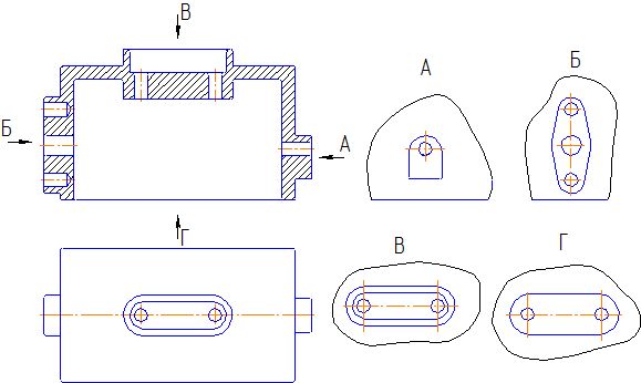
28.3. Additional views. The standard allows the use of, in addition to the main projection planes (cube faces), additional ones - to depict such elements of parts that are projected onto the main planes with distortion (Fig. 180, a). An additional plane is placed parallel to the surface of the part element whose image needs to be made (Fig. 180, b). Then it is combined with the main projection plane. The image obtained on this plane is called additional view.
In Figure 180, the left part of the part is not shown in the top view, since when projected onto a horizontal plane it appears distorted. The additional view gives an undistorted idea of the shape and dimensions of this part of the part.

Rice. 180
In the drawing, the additional view is marked with the inscription type A, and the direction of view is indicated in the drawing by an arrow with the same letter designation.
It is allowed to rotate the additional view (Fig. 180, d).
At the same time, a “rotated” sign is added to the inscription, placing it next to the letter.
In the case when the additional view is located in a projection connection, as is done in Figure 180, c, it is not designated or signed.
- In what cases is an additional type used?
- How to choose a plane for construction additional type?
28.4. Image of smooth transitions. The lines of mutual intersection of surfaces (Fig. 181, a) on technical drawings can be shown in a simplified manner (if their precise construction is not required). Thus, the line of intersection of two cylinders in the drawing can not be constructed using points to draw it along the pattern, but can be done using a compass (Fig. 181, b). In this case, the pattern curve is replaced by a circular arc. IN in some cases curved lines are replaced with straight ones (Fig. 181, c).

Rice. 181
In the drawing, a smooth transition from one surface to another can be depicted with a continuous thin line, without bringing it to the contour of the surface (see Fig. 181, c). Sometimes a smooth transition may not be shown at all (Fig. 182).

Rice. 182
- Why do you think smooth transition lines are allowed to be shown in a simplified manner?
- What lines in the drawing are allowed to replace curved pattern lines?
28.5. Text and symbol information on drawings. The drawing, as was established earlier, is a set of graphic and symbolic components that provide complete information about the product. In addition to the image, dimensions of the part, and the name of the material, some drawings also contain data on its processing.
It is known that with any method of manufacturing a part, its surface will not be completely smooth. The totality of all irregularities that form the surface relief is called roughness. The degree of surface roughness in the drawing is indicated by special signs. Together with the sign indicate the value of the parameter or numeric value roughness (see Fig. 2).
On the technical drawings you can also see dimensional numbers with additional entries: +0.5; Ø60 ±0.02, etc. What do they mean?
It is almost impossible to produce a part with absolutely accurate dimensions. As a result, the dimensions will be slightly different than the given ones. Therefore, in the drawing, next to the dimensional number, the deviation of the size from the given one or the limit numbers between which the dimensions can fluctuate are indicated.
GOST also establishes other signs that characterize the part or explain its geometric shape.
- What inscriptions may be contained on the drawings?
- Which conventional signs used in drawings to indicate surface roughness?
All this depends on many factors, but is primarily determined by the complexity of the geometric shape of the product, its size, as well as the requirements placed on it. You should strive for a minimum number of images and their simplicity without compromising the ease of reading the drawing - the most important requirement of production.
Thus, the geometric shape of a part limited by surfaces of rotation or the simplest combinations of them can be determined by a single image (see Fig. 7.5 and 7.86). Here the question may arise: what is advisable to use - a section, connecting part of a view with a part of the corresponding section, a view with drawing lines of an invisible contour?

Practice shows that the most understandable, but also the most labor-intensive is a complete section (Fig. 7.87, a), less understandable, but also less labor-intensive - connecting part of the view with the corresponding part of the section (Fig. 7.87,6,0), even less understandable , but also less labor-intensive - a view with lines of an invisible contour applied to it (Fig. 7.87, d). More and more wide application plotters makes the design of the drawing according to Fig. 7.87, d is acceptable, but it should be used, in particular, in cases where it is possible to avoid the use of invisible contour lines for applying dimensions, roughness marks, marking bases, etc. (Fig. 7.88).

Local (partial) views (Fig. 7.89), extensions and sections (see Fig. 7.19), cliffs (Fig. 7.90), halves of symmetrical images (Fig. 7.91) should be used as widely as possible.

However, it is inappropriate, for example, symmetrical top views in Fig. 2.56 and 7.91, replace them with halves, as this will make it difficult for the modeler to understand the drawing.

The correct choice of the main image largely depends on rational decision drawing. But the main image (correctly selected) can be oriented differently on the drawing plane. Therefore, when orienting it, you need to think about other necessary images so that, if possible, it is not necessary to draw invisible contour lines on them (Fig. 7.92, a, b), so that it is convenient to put down dimensions and apply roughness marks.

In Fig. 7.93 two solutions for the roller drawing are given: in A4 format and A3 format. Both solutions do not contradict clause 1.3 of GOST 2.305-68. Solution “a” may even be preferable to solution “b” if the roller is made on a vertical lathe. Executing training drawings of parts limited by surfaces of rotation according to scheme “a” is quite acceptable if this allows you to significantly reduce the consumption of drawing paper. However, we must remember that long drawings are more convenient to read when the main inscription is located along larger side format.

Covers, bearing housings, struts and other similar parts made by casting are usually depicted so that the main machined plane (design base) receives a horizontal position in the drawing. From this base, dimensions are set (taking into account auxiliary design bases) to the surfaces formed by removing a layer of material ( machining). The dimensions that determine the casting before its processing are entered from their foundry bases - the main and auxiliary ones.


In Fig. 7.91, the main design and foundry bases are conventionally marked with blackened triangles for clarity. To increase the strength of castings, so as not to increase the wall thickness, stiffeners are used (in Fig. 7.91 there are two of them, right and left, 6 mm thick). Technical requirements placed on the drawings parts made by casting (the main part of them for cast iron are shown in Fig. 7.91), in training drawings are usually limited to the requirements of paragraphs 2 and 3. Molding slopes are attached to the surfaces if the castings do not have structural slopes that ensure easy removal of the model from the mold. Instead of referring to GOST 3212-80*, they can be specified in the drawing in degree values (10...30) depending on the size of the surface height and the casting method. As a rule, only structural slopes are shown in the drawings (such as, for example, a cone 0 34 in Fig. 7.91), noting the requirements for molding slopes in the TT. Cast parts are also characterized by smooth gradual transitions from one surface to another (Fig. 7.94). Image of developments in the drawings of parts obtained by bending, as well as instructions on the dimensions of the part They are not given in expanded form. The development drawing, if necessary, can be issued as a technological document and is not included in the set of design documentation. However, if the image of a part manufactured flexible does not give an idea of the shape and dimensions of its individual elements, its full or partial development is placed on the drawing, indicating the dimensions that it is impossible to indicate the details in the image (Fig. 7.95, a). If all three holes are cut out during stamping, then a full development is required (Fig. 7.95,6). It is possible to combine the image of part of the development with the view (see Fig. 2.8, a and 7.96). When choosing the scale of images, you must be guided by the ease of reading them, and avoid thickening of dimension lines, surface roughness designations and other signs, taking into account that the larger the drawing format, the less convenient it is to use. In Fig. 7.97 shows a working drawing. The escape wheel is shown in M 20:1, the teeth are shown in M 200:1, A3 format. The drawing is user friendly. (The entry HV 460-510 indicates the required Vickers hardness.) Inscriptions and signs applied to flat surface the object, regardless of the method of their application, is depicted in the corresponding view in full (Fig. 7.98). 
If inscriptions and signs must be applied to a cylindrical or conical surface, then an image of the inscription in the form of a scan is placed on the drawing. Indicate the method of applying inscriptions and signs (engraving, stamping, embossing, etc.), covering the background, inscriptions and signs, and other information (Fig. 7.99).

In Fig. 7.100 shows a drawing of a stamped part with bends, flanges (holes with concave sides) and extrusions (rifts). When making drawings of such parts, it is necessary to use GOST 17040-80*, which contains size ranges the indicated elements (D, R, etc.). So, the question of the number of images, their content, relative position, scale, etc. is decided comprehensively based on the conditions for ease of use of the drawing. 
A correctly executed drawing is visual and carries a large amount of information that is understandable to a specialist. Therefore, all drawings are carried out in accordance with established and applied rules in all areas of activity. They are based on the combined achievements of science, technology and practical experience. The result of this work is standard.
In engineering graphics, standards are presented in the form of documents containing a number of requirements and norms established for general and repeated use.
In our country there are state standards(GOST) established for all products, as well as norms, rules, requirements, concepts, designations, etc.
To perform this calculation and graphic work, it is necessary, in addition to knowledge of the standards for the design of drawings, to study and be able to apply standards for the rules for depicting objects and applying dimensions in drawings, the rules for depicting shading and depicting axonometric projection.
The rules for depicting objects in drawings are established by GOST 2.305-68 “Images - views, sections, sections.”
Images of objects are made using the method of rectangular (orthogonal) projection. In this case, the object is located between the observer and the corresponding projection plane. The main projection planes are the six faces of the cube, aligned with the plane in accordance with Figure 6.
Figure 6 - Location of main views in the drawing
The number of images should be the smallest, but providing a complete picture of the subject when using the symbols, signs and inscriptions established in the relevant standards.
To reduce the number of images, it is allowed to show the necessary invisible parts of the surface of an object in views using dashed lines in accordance with Figure 7.

Figure 7 - Image of an object indicating invisible parts
Kinds
View– called the image of the visible part of the surface of an object facing the observer.
The following are installed basic views obtained on the main projection planes:
Image on the frontal plane of projections - front view ( main view);
Image on horizontal plane projections – top view;
Image on the profile projection plane – left view;
Right view;
Bottom view;
Back view.
The image of an object on the frontal projection plane is called main view. This image should give the most complete idea of the shape and size of the item.
The names of views on the drawings are not indicated if they are made in projection connection
If the projection connection is broken or the view is not located in the appropriate place, then the direction of projection should be indicated by an arrow at the corresponding view. The same capital letter of the Russian alphabet should be placed above the resulting image and the arrow in accordance with Figure 8.

Figure 8 – Types and simple sections, and their designations in the drawing
If any part of the object cannot be shown on the main projection planes without distorting the shape, use additional types, which are obtained on planes not parallel to the main planes of projections. Additional views are designated similarly to views on the main projection planes. An additional view located in direct projection connection with the corresponding image is not indicated, and the direction of projection is not indicated. It is possible to rotate the additional view to the position adopted for the object in the main image. In this case, the type designation must be supplemented with a conventional graphic designation - the “rotated” sign (Fig. 9). If necessary, indicate the value of the rotation angle.

Figure 9 – Additional view designation
Local view An image of a separate, limited area on the surface of an object is called.
Local view may or may not be limited by the cliff line, if it is necessary to read the shape of the protruding part of the object (Fig. 8). The detail view should be indicated on the drawing in a manner similar to the supplementary view.
Rules for depicting objects (products, structures and their constituent elements) on drawings for all industries and construction is established by GOST 2.305 - 2008 * “Images - views, sections, sections”.
Images of objects must be made using the rectangular (orthogonal) projection method. In this case, the object is placed between the observer and the corresponding projection plane. When constructing images of objects, the standard allows the use of conventions and simplifications, as a result of which the specified correspondence is violated. Therefore, the resulting figures when projecting an object are called not projections, but images. The faces of a hollow cube are taken as the main projection planes, into which an object is mentally placed and projected onto internal surfaces faces. The faces are aligned with the plane (Figure 2.1). As a result of this projection, the following images are obtained: front view, top view, left view, right view, rear view, bottom view.
The image on the frontal plane is taken as the main one in the drawing. The object is positioned relative to the frontal plane of projections so that the image on it gives the most complete idea of design features object and its functional purpose.
Let's consider main image selection using the example of an object such as a chair. Let us depict its projections schematically:
Let's think: the functional purpose of the object is to sit on it. In which of the figures this purpose is most clear - probably this is figure 1 or 2, the 3rd is the least informative.
The design features of the item include a seat itself, a backrest for the convenience of sitting on a chair, located at a certain angle relative to the seat, legs that position the seat at a certain distance from the floor. Which of the figures shows these features most clearly? Obviously this is Figure 1.
Conclusion - we choose projection number 1 as the main view, as it is the most informative and provides the most complete information about the functional purpose of the chair and its design features.
It is necessary to think in a similar way when choosing the main image of any subject!
The images in the drawing, depending on their content, are divided into types, sections, sections.
View - image of the visible part of the surface of an object facing the observer.
Types are divided into basic, local and additional.
Main types — images are obtained by projecting an object onto a projection plane. There are six of them in total, but more often than others, I use the main three to obtain information about the subject: horizontal π 1, frontal π 2 and profile π 3 (Figure 2.1). With this projection we get: front view, top view, left view.
The names of views on the drawings are not inscribed if they are located in a projection relationship (Figure 2.1). If the views from above, to the left and to the right are not in projection connection with the main image, then they are marked on the drawing with an inscription of type “A”. The direction of view is indicated by an arrow, indicated by a capital letter of the Russian alphabet. When there is no image that can show the direction of view, the name of the species is inscribed.


Figure 2.1 Formation of main species
Local view - an image of a separate limited area of the surface of an object on one of the main projection planes. The local view can be placed in any free space of the drawing, marked with an inscription like “A”, and the associated image of the object should have an arrow indicating the direction of view, with the corresponding letter designation (Figure 2.2 a, b).
 |
| A |
 |
| b |
Figure 2.2 – Local species
The local species may be limited to the cliff line, in the smallest possible size (Figure 2.2, a), or not limited (Figure 2.2, b).
Additional views— images obtained on planes non-parallel to the main planes of projections. Additional views are performed in cases where any part of the object cannot be shown in the main views without distorting its shape and size. The additional view is marked on the drawing with an inscription of type “A” (Figure 2.3, a), and an arrow with the corresponding letter designation is placed next to the additional view of the image of the object (Figure 2.3, a), indicating the direction of view.
When an additional view is located in direct projection connection with the corresponding image, the arrow and inscription above the view are not applied (Figure 2.3, b). The secondary view can be rotated while maintaining the same position as the item in the main image. In this case, a sign (“Rotated”) is added to the inscription “A” (Figure 2.3, c).
Basic, local and additional views are used to depict the shape of the external surfaces of an object. A successful combination of them allows you to avoid dashed lines, or reduce their number to a minimum. To reduce the number of images, it is allowed to show the necessary invisible parts of the surface in views using dashed lines. However, identifying the shape of the internal surfaces of an object using dashed lines significantly complicates reading the drawing, creates preconditions for its incorrect interpretation, complicates drawing dimensions and symbols therefore their use should be limited and justified. To identify the internal (invisible) configuration of an object, conventional images are used - cuts and sections.
Figure 2.3
2.2 Sections
A section is an image of an object mentally dissected by one or more planes.
The section shows what is located in the secant plane and what is located behind it.
2.2.1 Classification of cuts
Depending on the number of cutting planes The sections are divided into (Figure 2.4):
- simple— with one cutting plane (Figure 2.6);
- complex— with several cutting planes (Figure 2.9, 2.10).

Figure 2.4 - Classification of cuts
The position of the cutting plane is shown in the main image with a thick open line (1.5s, where s– thickness of the main line). The length of each stroke is from 8 to 20 mm. The direction of view is shown by arrows perpendicular to the strokes. Arrows are drawn at a distance of 2-3 mm from the outer ends of the strokes. The name of the cutting plane is indicated in capital letters of the Russian alphabet. The letters are applied parallel to the horizontal lines of the main inscription, regardless of the position of the arrows (Figures 2.5, 2.6, 2.9, 2.10, 2.11).
If, when making a simple cut that is in projection connection with the main image, the cutting plane coincides with the plane of symmetry, then the cutting plane is not depicted and the cut is not labeled.

Figure 2.5 – Designations of sections in the drawing

Figure 2.6 - Simple section: a) - frontal; b) - local
Depending on the cutting plane position relative to the horizontal plane of projections, the sections are divided into:
- horizontal — the secant plane is parallel to the horizontal plane of projections (Figure 2.7, b);
- vertical – the secant plane is perpendicular to the horizontal plane of projections (Figure 2.7, c, d);
- inclined– the secant plane makes an angle with the horizontal projection plane that is different from the right angle (Figure 2.8).

Figure 2.7 a – Model of the “Crank” part


Figure 2.7 b - Simple horizontal section
Vertical the cuts are called:
- frontal , if the cutting plane is parallel to the frontal plane of projections (Figure 2.7, c);
- profile, if the cutting plane is parallel to the profile plane of projections (Figure 2.7, d).


Figure 2.7 c – Simple frontal section


Figure 2.7 d - Simple profile section


Figure 2.8 – Oblique section
Complex cuts are divided into:
- stepped , if the cutting planes are parallel (stepped horizontal, stepped frontal) (Figure 2.9);
- broken lines, if the cutting planes intersect (Figure 2.10).

Figure 2.9 - Complex - Stepped cut

Figure 2.10 - Complex - Broken cut
The cuts are called:
- longitudinal, if the cutting planes are directed along the length or height of the object (Figure 2.7, c);
- transverse, if the cutting planes are directed perpendicular to the length or height of the object (Figure 2.7, d).
Sections that serve to clarify the structure of an object only in certain, limited places are called local .


Figure 2.11 a - Examples of making cuts

Figure 2.11 b - Examples of making sections combined with views
2.2.2 Making cuts
Horizontal, frontal and profile sections can be located in place of the corresponding main views (Figure 2.11, a, b).
Part of the view and part of the corresponding section can be connected by separating them with a solid wavy line or a line with a break (Figure 2.11, b). It should not coincide with any other lines in the image.
If half of the view and half of the section are connected, each of which is a symmetrical figure, then the dividing line is the axis of symmetry (Figures 2.11, b; 2.12). You cannot connect half a view with half a section if any line of the image coincides with the axial line (for example, an edge). In this case, connect most of the species with a smaller part of the section or most of the section with a smaller part of the species.
It is allowed to separate the section and the view by a thin dash-dotted line coinciding with the trace of the plane of symmetry not of the entire object, but only of its part, if it represents a body of rotation. When connecting half of the view with half of the corresponding section, the section is located to the right of the vertical axis and below the horizontal (Figure 2.12).

Figure 2.12

Figure 2.13
Local cuts are highlighted in the view as solid wavy lines. These lines should not coincide with any other lines in the image (Figure 2.13).
Sectional figures obtained by different cutting planes when performing complex cut, do not separate one from the other by any lines.
A complex stepped section is placed in place of the corresponding main view (Figure 2.9) or anywhere in the drawing.
With broken cuts, the secant planes are conventionally rotated until they align into one plane, and the direction of rotation may not coincide with the direction of view. If the combined planes turn out to be parallel to one of the main projection planes, then the broken section can be placed in the place of the corresponding type (Figure 2.10).
When rotating the cutting plane, the elements of the object located behind it are drawn as they are projected onto the corresponding plane with which the alignment is made. It is allowed to connect a stepped cut with a broken one in the form of one complex cut.
2.3 Sections
Section called the image of a figure obtained by mentally dissecting an object with a cutting plane(Figure 2.14).
The section shows only what falls directly into the cutting plane.
The cutting planes are chosen so as to obtain normal cross sections.
Sections are divided into:
- sections included in the section (Figure 2.15, a);
- sections not included in the section Figure 2.15.b).
Sections not included in the composition are divided into:
- issued(Figures 2.14, a; 2.14, c; 2.15, b; 2.16, a; 2.17, a; 2.18);
- superimposed(Figures 2.14, b; 2.16, b; 2.17, b).
Extended sections are preferable and they can be located in the gap between parts of the same type, on the continuation of the trace of the cutting plane with a symmetrical section figure, at any place in the drawing field, as well as with a rotation (Figures 2.14, a, c; 2.15, b; 2.16, a; 2.17, a; 2.18, a).
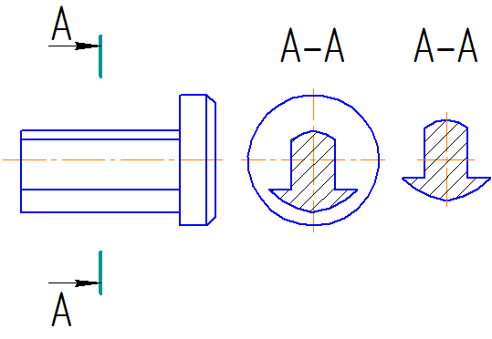
To depict the trace of the cutting plane in the drawing, use a thick open line with arrows indicating the direction of view, and designate the cutting plane in capital letters of the Russian alphabet. The section is accompanied by an inscription according to type A-A(Figure 2.14).
The ratio of the sizes of the arrows and the strokes of the open line must correspond to Figure 2.14. The starting and ending strokes must not intersect the outline of the image.
Letter designations are assigned in alphabetical order without repetition and, as a rule, without gaps. The font size of the letter designations must be approximately two times larger than the size of the digits of the size numbers. The letter designation is located parallel to the main inscription, regardless of the position of the cutting plane.
IN general case, when the section is located in any free space in the drawing, the position of the trace of the cutting plane is depicted as indicated above, and the image of the section is accompanied by an inscription corresponding to the name of the cutting plane (Figure 2.14, a; 2.15, b).
In the cases shown in Figures: 2.14, b, c; 2.17, a, b; 2.18, a (superimposed sections; sections made in a break in the view; sections made on the continuation of the trace of the cutting plane) - for symmetrical sections the trace of the cutting plane is not depicted and the section is not accompanied by an inscription.

Figure 2.14 A

Figure 2.14 b

Figure 2.14 V
For asymmetrical sections , located in a gap, or superimposed, the trace of the cutting plane is depicted, but not accompanied by letters (Figure 2.16). The section is also not accompanied by an inscription.
The outline of the extended section is drawn with a thick solid line (the main line), and the outline of the superimposed section is drawn with a thin solid line, while the outline of the view is not interrupted.
 |
|
| A | b |
Figure 2.15
 |
|
| A | b |
Figure 2.16

Figure 2.17 A,b
 |
|
| A | b |
Figure 2.18
For several identical sections of the same object, the section lines are designated by one letter and one section is drawn. If the cutting planes are directed at different angles, then the “Rotated” sign is not applied (Figure 2.19).

MECHANICAL ENGINEERING DRAWING
Basic requirements of ESKD for the design of drawings
All drawings must be carried out in strict accordance with the rules established by the ESKD. The design of drawings includes standards for formats, scales, lines, drawing fonts, and main inscriptions.
Formats
When making drawings for each of them, the basic formats established by the GOST 2.301-68 standard are used.
The designations and dimensions of the sides of the main formats must comply with the instructions in Table 1.
Table 1 - Formats
If necessary, it is allowed to use A5 format with side dimensions of 148 x 210 mm.
Inside the outer frame, each drawing is framed by a working field frame, which is drawn with a solid thick line at a distance of 20 mm from the left side of the format, necessary for filing sheets of the design document, and 5 mm on the other three sides of the format.
Scale
After determining the working field of the drawing, depending on the complexity and size of the product, the image in the drawing is made in the appropriate scale established by GOST 2.302-68.
Scale– this is the ratio of the dimensions of the image in the drawing to the corresponding actual (natural) dimensions of the product.
The scale of the image in the drawings must be selected from the standard range according to Table 2.
Table 2 - Standard series of scales
The selected scale should provide a clear image of the product and its structural elements.
The scale of the images is indicated in the corresponding column of the main inscription of the drawing by type: 1:1; 1:2; 2:1 etc.
If the scale of any image in the drawing differs from that indicated in the main inscription, then its designation is placed above the corresponding image according to the type: M1:1; M1:2; M2:1.
Lines
To make drawings easier to read, nine types of lines established by GOST 2.303-68 are accepted.
Types of lines and their main purposes are shown in Table 3.
Table 3 - Line types


All visible contours of the product are made with a solid thick main line. Depending on the drawing format, size and complexity of the image, the thickness of the main line s accepted from 0.5 to 1.4 mm. The thicknesses of all other types of lines depend on the thickness of the solid thick main line adopted in this drawing. The thickness of the open line should be 1.5 times thicker than the main line, and all other lines should be 2 or 3 times thinner than the main line.
For drawings made at the student stage of development, the thickness of a solid thick line is sufficient to take from 0.8 to 1 mm.
The thickness and brightness of lines for the same purpose should be the same for all images in the drawing, made to the same scale.
The length of strokes in dashed and dash-dotted lines should be selected depending on the size of the image.
In a dashed line, the stroke length is taken from 2 to 8 mm, the distance between strokes is from 1 to 2 mm.
Dash-dotted lines must begin, intersect, and end with dashes. Strokes and lines must be the same length, and the spaces between strokes must be the same. The length of the dash-dotted thin line should be from 5 to 30mm, thick - from 3 to 8mm. The spaces between strokes should be: for a thin line-dotted line - from 3 to 5mm, for a thick line - from 3 to 4mm. Dot-dash lines used as center lines should be replaced with solid thin lines if the diameter of the circle or the size of other geometric shapes in the image is less than 12 mm.
The length of the open line stroke should be from 8 to 20mm.
Drawing fonts
Drawing fonts used for all inscriptions on drawings and other technical documents, established by GOST 2.304-81.
The drawing font contains Russian, Latin and Greek alphabets, Arabic and Roman numerals, and symbols.
The following font sizes are set: 2.5; 3.5; 5; 7; 10; 14; 20; 28; 40. They are determined by height h capital letters in millimeters, measured perpendicular to the base of the line. Letter width g– the largest width of a letter, which is determined in relation to the font size h, For example, g=6/10 h.
The standard sets following types fonts:
type A without slant (font line thickness d=1/14 h);
type A with an inclination of about 75° ( d=1/14 h);
type B without tilt ( d=1/10 h);
type B with an inclination of about 75° ( d=1/10 h) (Fig. 1).
The shape of the letters of the Russian alphabet and Arabic numerals must be the same for the entire inscription. When making drawings in pencil, the recommended height of capital letters and numbers is 5mm. For various inscriptions on mechanical engineering drawings, it is preferable to use type A with an inclination in accordance with Figure 1.

Figure 1 – Design of font types A And B
Basic inscriptions
All the above information is necessary for correct design images and main inscriptions on the drawings.
The shape, dimensions and procedure for filling out the main inscriptions in design documents are determined by GOST 2.104-68.
There are main inscriptions for drawings and diagrams - form 1 (Fig. 2), and main inscriptions for text documents - form 2 (Fig. 3) on the first or title sheet and form 2a (Fig. 4) on subsequent sheets of text documents, and also on subsequent sheets of drawings and diagrams.
The following data is provided in the main inscription columns.
Column 1 contains the name of the product. The name of the product must be short and written in the nominative singular case. Do not put a period at the end of the name. In a name consisting of several words, the noun is placed first.
Column 2 contains the designation of the document. This column is filled in at enterprises in accordance with the requirements of GOST 2.201-80. On educational drawings, the designation is established by the corresponding department. Figure 5 shows an example of filling out the main inscription at the Department of Engineering Graphics of USPTU.
In column 3 - product material according to GOST for material (filled out only on part drawings).
In column 4 - put down the drawing letter assigned this document. On training drawings the letter “ at"- educational. The letter is entered in the left column.
In column 5 - the mass of the product shown in the drawing. The mass is indicated as theoretical or practical in kg.
Column 6 shows the image scale.
In column 7 - serial number leaf. If all images are made on one sheet, then the column is not filled out.
Column 8 shows the total number of sheets of the document. The column is filled in only on the first sheet.
In column 9 - the name of the company that issued the drawing.
Column 10 indicates the nature of the work performed by the person who signed the document.
Column 11 contains the names of the persons who signed the document.
In column 12 - signatures of persons whose surnames are indicated in column 11.
Column 13 indicates the date of signing the document.
The remaining columns on the training drawings are not filled in.

Figure 2 - Main inscription form 1.
For drawings and diagrams

Figure 3 - Main inscription form 2.
For text design documents
(first or title page)

Figure 4 - Main inscription form 2a.
For design documents
(subsequent sheets)

Figure 5 - Example of document designation
The main inscription is made with basic and continuous thin lines.
The main inscription is located in the lower right corner of the design documents. On A4 sheets, the main inscription is placed along the short side of the format, since this format is used only with the long side vertical. In this case, the main inscription fits exactly into the frame of the working field of the drawing. Sheets of other formats are placed with the long side both horizontally and vertically.
Table 4 - Font sizes and type of letters for filling out the main inscription columns
| Count | Font size | Type of letters | Note |
| Lowercase | For naming documents, font 5 | ||
| Uppercase | |||
| Lowercase and uppercase | |||
| Uppercase | |||
| 5 and 6 | Uppercase | ||
| 7 and 8 | 3,5 | Uppercase | |
| Lowercase and uppercase | On the top line | ||
| 3,5 | Bottom line | ||
| Rest | 3,5 | Lowercase | |
Images on drawings
A correctly executed drawing is visual and carries a large amount of information that is understandable to a specialist. Therefore, all drawings are carried out in accordance with established and applied rules in all areas of activity. They are based on the combined achievements of science, technology and practical experience. The result of this work is standard.
IN engineering graphics standards are presented in the form of documents containing a number of requirements and norms established for general and repeated use.
In our country, there are state standards (GOST) established for all products, as well as norms, rules, requirements, concepts, designations, etc.
To perform this calculation and graphic work, it is necessary, in addition to knowledge of the standards for the design of drawings, to study and be able to apply standards for the rules for depicting objects and applying dimensions in drawings, the rules for depicting shading and depicting axonometric projection.
The rules for depicting objects in drawings are established by GOST 2.305-68 “Images - views, sections, sections.”
Images of objects are made using the method of rectangular (orthogonal) projection. In this case, the object is located between the observer and the corresponding projection plane. The main projection planes are the six faces of the cube, aligned with the plane in accordance with Figure 6.

Figure 6 - Location of main views in the drawing
The number of images should be the smallest, but providing a complete picture of the subject when using the symbols, signs and inscriptions established in the relevant standards.
To reduce the number of images, it is allowed to show the necessary invisible parts of the surface of an object in views using dashed lines in accordance with Figure 7.

Figure 7 - Image of an object indicating invisible parts
Kinds
View– called the image of the visible part of the surface of an object facing the observer.
The following are installed basic views obtained on the main projection planes:
1. Image on the frontal plane of projections - front view (main view);
2. Image on a horizontal projection plane – top view;
3. Image on the profile projection plane – left view;
4. Right view;
5. Bottom view;
6. Rear view.
The image of an object on the frontal projection plane is called main view. This image should give the most complete idea of the shape and size of the item.
The names of views on the drawings are not indicated if they are made in projection connection
If the projection connection is broken or the view is not located in the appropriate place, then the direction of projection should be indicated by an arrow at the corresponding view. The same capital letter of the Russian alphabet should be placed above the resulting image and the arrow in accordance with Figure 8.

Figure 8 - Types and simple sections, and their designations in the drawing
If any part of the object cannot be shown on the main projection planes without distorting the shape, use additional types, which are obtained on planes not parallel to the main planes of projections (Fig. 9). Additional views are designated similarly to views on the main projection planes (Fig. 9). An additional view located in direct projection connection with the corresponding image is not indicated, and the direction of projection is not indicated. It is possible to rotate the additional view to the position adopted for the object in the main image. In this case, the type designation must be supplemented with a conventional graphic designation ã - the “rotated” sign (Fig. 9). If necessary, indicate the value of the rotation angle.

Figure 9 – Additional view designation
Local view An image of a separate, limited area on the surface of an object is called.
The local view may or may not be limited to the cliff line if it is necessary to read the shape of the protruding part of the object (Fig. 8, 9). The detail view should be indicated on the drawing in a manner similar to the supplementary view.
Cuts
To identify internal structure The object in the drawings is made with cuts and sections.
By cut is an image of an object mentally dissected by one or more planes. In this case, mental dissection relates only to this cut and does not entail changes in other images of the same object. The section shows what is obtained in the secant plane and what is located behind it (Fig. 8). It is allowed to show not everything that is located behind the cutting plane, if this is not required to understand the design of the object.
Depending on the number of cutting planes, the sections are divided into simple - with one cutting plane (Fig. 8) and complex – with several cutting planes (Fig. 10, 11).
Depending on the position of the cutting planes, simple cuts are divided into horizontal, if the cut plane is parallel to the horizontal projection plane, vertical(Fig. 8), inclined, if the cutting plane is not parallel to any of the main projection planes. The vertical cut is called frontal, if the cutting plane is parallel to the frontal plane of projections and profile, if the cutting plane is parallel to the frontal plane of projections.
Difficult cuts include stepped, when the cut planes are parallel to each other (Fig. 10), and broken lines, if the cutting planes intersect at an angle greater than 90° (Fig. 11).

Figure 10 - Stepped section
The position of the secant plane of the section is indicated in the drawing using an open section line in accordance with GOST 2.303-68. The starting and ending strokes of the section line are drawn outside the outline of the image. In the case of a stepped cut, strokes are also drawn at the places where the cutting planes transition to another level, and on broken cuts - at the intersection of the cutting planes. On the initial and final strokes, perpendicular to them, at a distance of 2...3 mm from the outer end of the stroke, arrows are placed indicating the direction of view. Outside the arrows, identical capital letters of the Russian alphabet are applied. In this case, an inscription of the “AA” type is made above the corresponding image of the section.
When the secant plane coincides with the plane of symmetry of the object as a whole, and the corresponding images are located on the same sheet in direct projection connection and are not separated by any other images, for horizontal, frontal and profile sections the position of the secant plane is not marked, and the cut is inscribed not accompanied (Fig. 8)
Horizontal, frontal and profile sections, as a rule, are located in place of the corresponding main views.
A vertical section, when the cutting plane is not parallel to the frontal or profile planes of projections, as well as an inclined section, must be constructed and located in accordance with the direction indicated by the arrows on the section line. It is allowed to place such sections at any place in the drawing, as well as with rotation to a position corresponding to that accepted for a given item in the main image. In the latter case, a conditional must be added to the inscription graphic designationã - “rotated” sign.
In the image of a broken section, the secant planes are conventionally rotated until they are aligned into one plane, and the direction of rotation may not coincide with the direction of view. If the combined planes turn out to be parallel to one of the main projection planes, then the broken section can be combined in place of the corresponding type (Fig. 11). When rotating the secant plane, the elements of the object located behind it are drawn as they are projected onto the corresponding plane with which the alignment is made.

Figure 11 - Broken section
An incision that serves to clarify the structure of an object in a separate, limited place is called local. Local cut stands out in the form of a solid wavy line (Fig. 8, 12) or a thin one with kinks, according to GOST 2.303-68. These lines must not coincide with any other lines in the image.
For symmetrical images, you can connect half the view and half the section, and if the axis of symmetry is vertical, then, as a rule, the view is placed on the left, and the section on the right (Fig. 12). If the axis of symmetry is horizontal, then the top is the view, the bottom is the section. The dividing line between them is the axis of symmetry - a thin dash-dotted line.

Figure 12 - Connection of part of the view and part of the section
In the absence of symmetry or when the axis of symmetry of the part coincides with any contour line, for example with an edge, part of the line and part of the cut should be separated by a wavy line or a line with breaks drawn on one side or another of the axis of symmetry (Fig. 13). In this case, the line with a break should extend beyond the outline of the image.

Figure 13 - Combining part of the view and part of the section
Sections
Section is the image of a figure resulting from the mental dissection of an object by one or more planes. The section shows only what is obtained directly in the cutting plane.
It is allowed to use as a secant cylindrical surface, which is then developed into a plane. The designation of the image is accompanied by a conventional graphic sign ä - “expanded”.
Sections not included in the section are divided into issued(Fig. 14 b, c) and superimposed(Fig. 14 a).

Figure 14 - Section: a – superimposed; b, c – taken out.
Exposed sections can be located anywhere in the working area of the drawing, also in the gap between parts of the same type. The axis of symmetry of the extended or superimposed section is indicated by a dash-dot line without designation, letters and arrows, and the section line is not drawn (Fig. 14).
For asymmetrical sections located in a gap or superimposed (Fig. 15), the section line is drawn and arrows are drawn, but letters are not placed. In all other cases, the designation of the section line and the section itself is carried out in the same way as for the section. The cutting planes are chosen so as to obtain normal cross sections.

Figure 15 - Asymmetrical section: a – extended; b – in a gap; c – superimposed.
The section in construction and location must correspond to the direction indicated by the arrows. It is allowed to place the section on any field of the drawing, as well as with a rotation and the addition of a sign (for example, A-A).
If the cutting plane passes through the axis of the surface of rotation that bounds the hole or recess, then the contour of the hole or recess in the section is shown in full (Fig. 14).
The contour of the extended section, as well as the section included in the section, is outlined with solid main lines, and the contour of the superimposed section is outlined with solid thin lines.
If the section turns out to consist of separate independent parts, a section should be drawn.
In the images of sections and sections in places where the plane of the material of the part is cut, depending on the type of material, shading is performed in accordance with GOST 2.306-68. If the part is made of metal, then the shading is applied in continuous thin parallel lines at an angle of 45° to the drawing frame lines in the same direction on all sections of the same part. If the contour lines of the part or the center lines are located at an angle of 45° to the lines of the drawing frame, then the angle of inclination of the hatch lines should be taken at 30° or 60°. The distance between the hatching lines must be the same for all sections of a given part and can be selected in the range from 1 to 3 mm depending on the hatching area.
If the secant plane runs along a thin wall or stiffener rib of a part, then such a wall or rib is conditionally not hatched (Fig. 8).
The height of the letters in the designations of types, sections and sections should be one or two sizes larger than the height of the dimensional numbers adopted in this drawing. Minimum diameter signs “rotated” and “expanded” is 5mm.
Applying dimensions
All images are accompanied by dimensions. When applying dimensions, you should be guided by the basic provisions of GOST 2.307-68 “Applying dimensions and maximum deviations”.
The dimensions of the true size of the part and its elements are indicated on the drawing, regardless of the scale of the image.
Linear dimensions are indicated on the drawing in millimeters without indicating a unit of measurement, angular dimensions - in degrees, minutes.
Dimensions in the drawings are indicated by dimensional numbers, extension and dimension lines (solid thin).
When applying the size of a straight segment, the dimension line is drawn parallel to this segment, extension lines are drawn perpendicular to the dimension lines (Fig. 16).

Figure 16 - Drawing linear and angular dimensions
When applying the size of an angle, the dimension line is drawn in the form of an arc with the center at its apex, and the extension lines are drawn radially (Fig. 21).
It is preferable to apply dimension lines outside the outline of the image. It is not allowed to use contour lines, axial, center and extension lines as dimension lines. It is necessary to avoid intersections of dimension and extension lines.
The dimension line is limited at both ends by arrows that abut extension lines (Fig. 17). The values of the elements of the dimension line arrows are selected depending on the thickness of the lines of the visible contour and they are drawn approximately the same throughout the entire drawing. The shape of the arrow and the approximate relationship of its elements are shown in Figure 17.

Figure 17 - Shapes and sizes of arrow elements
Extension lines are drawn from the visible contour lines. Extension lines should extend beyond the ends of the arrows of the dimension line by 1...5 mm (Fig. 16).
The distance between the contour line and the dimension line is selected depending on the size of the image and the saturation of the drawing. The minimum distance between the dimension line and the contour line should be 10 mm, and the minimum distance between parallel dimension lines should be 7 mm (Fig. 16).
Dimensional numbers are applied above the dimension line, as close as possible to its middle. When drawing several parallel dimension lines, the dimension numbers should be placed in a checkerboard pattern (Fig. 16).
Linear dimensions for various inclined dimension lines and angular dimensions, at different angle positions, they are applied as shown in Figure 21. If the dimensional number of a linear or angular size, applied above the middle of the dimension line, falls into the shaded areas (within an angle of 30°), then it is placed on a horizontal shelf of the leader line . For small corners with a lack of space, dimensional numbers are placed on the shelves of leader lines in any zone.
If there is not enough space to apply arrows and dimensional numbers, then they are applied using one of the methods shown in Fig. 18. If there is not enough space for arrows on dimension lines located in a chain, the arrows can be replaced with serifs applied at an angle of 45° to the dimension lines or clearly marked dots (Fig. 18). If there is not enough space for the arrow due to a closely located contour or extension line, the latter can be interrupted.

Figure 18 - Drawing dimension lines when there is not enough space for arrows
Dimensional numbers are not allowed to be divided or crossed by any drawing lines. At the place where the dimensional number is applied, the axial, center lines and hatch lines are interrupted (Fig. 19). Contour lines are not allowed to be interrupted.

Figure 19 - Drawing dimension lines and numbers during application contour lines and hatch lines.
Dimensions related to the same structural element(groove, protrusion, hole, etc.), it is recommended to group them in one place, placing them on the same image in which the geometric shape of this element is shown most fully (Fig. 20).

Figure 20 - Drawing hole dimensions in section
A capital letter is placed before the radius dimension number R, (For example, R20), before the diameter size number there is a ñ sign (for example, ñ 20 ).
If the radius is large, the center of the circular arc can be brought closer to the arc. In this case, the radius dimension line is shown with a break at an angle of 90Å. If it is not necessary to indicate the dimensions that determine the position of the center of the circular arc, then the radius dimension line may not be brought to the center and may be shifted relative to the center. When drawing several radii from one center, the dimension lines of any two radii are not placed on the same straight line.
In the case of making an image with a sphere, if it is difficult to distinguish it from other surfaces, it is allowed to apply the word “Sphere” or the sign when applying the diameter (radius) size of the sphere (for example, Sphere R15,ñ 40 ).
A square in the drawing is determined by two dimensions of its sides or one dimension with the sign ò (Fig. 21). Diagonals drawn by thin lines conventionally indicate a plane.
The dimensions of chamfers at an angle of 45Å are applied as shown in Figure 21. The dimensions of chamfers at other angles are indicated by linear and angular dimensions or two linear dimensions.

Figure 21 - Dimensions of part elements.
In the case of an image in the drawing in which the view is combined with a section (top or left view), as well as when drawing symmetrical figure to the axis of symmetry or with a break, the dimension line is drawn with a break, which is made further than the axis or break line of the image (Fig. 22).

Figure 22 - Drawing dimension lines with a break
The total number of sizes should be minimal, but sufficient for the manufacture and control of the product. The dimensions of the same element in the drawing are not allowed to be repeated. The dimensions of several identical elements of the product, as a rule, are applied once, indicating the number of these elements on the shelf or under it (Fig. 23). At the same time, for elements evenly spaced around the circle (for example, holes), angular dimensions are not placed between them, provided that one of these elements lies on one of the axes of symmetry (Fig. 23 a). Only the size of the diameter of the circle on which the centers of the holes are located (ñ 32 in Fig. 23 a). If none of the holes lies on the axis of symmetry, then you should set the angle to the first element (Fig. 23 b).

Figure 23 - Drawing dimensions of the size and location of holes on a circle: a - on the axes of symmetry; b – outside the axis of symmetry


