Well flow rate: determination and calculation. Methods for calculating oil flow rate Measuring the flow rate of gas wells and gas consumption
This concept means the amount of water, oil or gas that a source can produce per conventional unit of time - in a word, its productivity. This indicator is measured in liters per minute, or in cubic meters per hour.
Calculation of flow rate is necessary both when arranging household water-bearing wells, both in gas production and oil industry— each classification has a specific formula for calculations.
1 Why do you need to calculate the well flow rate?
If you know the flow rate of your well, you can easily select the optimal pumping equipment, since the pump power must exactly match the productivity of the source. In addition, in case of any problems, a correctly completed well passport will greatly help the repair team to choose suitable way its restoration
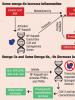
Based on flow rates, wells are classified into three groups:
- Low-rate (less than 20 m³/day);
- Average flow rates (from 20 to 85 m³/day);
- High-flow rates (over 85 m³/day).
In the gas and oil industries, the operation of low-yield wells is unprofitable. Therefore, preliminary forecasting of their flow rate is a key factor that determines whether a new gas well will be drilled in the developed area.
To determine such a parameter in the gas industry there is a certain formula (which will be given below).
1.1 How to calculate the flow rate of an artesian well?
To perform calculations, you need to know two source parameters - static and dynamic water levels.
To do this, you will need a rope with a voluminous weight at the end (so that a splash can be clearly heard when it touches the water surface).

Indicators can be measured after one day after completion. It is necessary to wait a day after completion of drilling and flushing so that the amount of liquid in the well stabilizes. It is not recommended to take measurements earlier - the result may be inaccurate, since during the first day there is a constant increase in the maximum water level.
After the required time has elapsed, take a measurement. This must be done in depth - determine how long the part of the pipe in which there is no water is. If the well is made in accordance with all technological requirements, then the static water level in it will always be higher than the top point of the filter section.
The dynamic level is a variable indicator that will change depending on the operating conditions of the well. When water is withdrawn from a source, its quantity in the casing constantly decreases. In the case when the intensity of water intake does not exceed the productivity of the source, then after some time the water stabilizes at a certain level.
Based on this, the dynamic level of liquid in a well is an indicator of the height of the water column, which will remain with constant liquid intake at a given intensity. When using different power the dynamic water level in the well will differ.
Both of these indicators are measured in “meters from the surface”, that is, the lower the actual height of the water column in the siege column, the lower the dynamic level will be. In practice, calculating the dynamic water level helps to determine the maximum depth to which a submersible pump can be lowered.
Calculation of the dynamic water level is carried out in two stages - you need to perform medium and intensive water intake. Take measurements after the pump has worked continuously for one hour.
Having determined both factors, you can already obtain approximate information on the flow rate of the source - the smaller the difference between the static and dynamic levels, the greater the well flow rate. Good artesian well these indicators will be identical, and the average productivity source has 1-2 meters of difference.

Calculation of well flow can be done in several ways. The easiest way to calculate the flow rate is using the following formula: V*Hv/Hdin – Hstat.
In which:
- V – intensity of water extraction when measuring the dynamic level of the well;
- N din – dynamic level;
- N stat – static level;
- H in – the height of the water column in the casing (the difference between total height casing and static fluid level)
How to determine the flow rate of a well in practice: let’s take as an example a well whose height is 50 meters, while the perforated filtration zone is located at a depth of 45 meters. The measurement showed a static water level of 30 meters deep. Based on this, we determine the height of the water column: 50-30 = 20 m.
To determine the dynamic indicator, assume that in one hour of operation the pump pumped two cubic meters of water from the source. After this, the measurements showed that the height of the water column in the well became 4 meters less (there was an increase in the dynamic level by 4 m)
That is, N din = 30+4=34 m.
In order to reduce possible calculation errors to a minimum, after the first measurement it is necessary to calculate the specific flow rate, with the help of which it will be possible to calculate the real indicator. To do this, after the first intake of liquid, it is necessary to give the source time to fill so that the level of the water column rises to a static level.
Then we take water at a higher intensity than the first time and measure the dynamic indicator again.
To demonstrate the calculation of specific flow rate, we use the following conditional indicators: V2 (pumping intensity) - 3 m³, if we assume that with a pumping intensity of 3 cubic meters per hour, Ndin is 38 meters, then 38-30 = 8 (h2 = 8).

The specific flow rate is calculated using the formula: Du = V 2 – V 1 / H 2 – H 1, where:
- V1 – intensity of the first water intake (lower);
- V2 – intensity of the second water intake (high);
- H1 – reduction of the water column when pumping at a lower intensity;
- H2 – decrease in the water column when pumping at higher intensity
We calculate the specific flow rate: D y = 0.25 cubic meters per hour.
The specific flow rate shows us that an increase in the dynamic water level by 1 meter entails an increase in the well flow rate by 0.25 m 3 /hour.
After the specific and ordinary indicators have been calculated, the real flow rate of the source can be determined using the formula:
Dr = (N filter – N stat) * Dn, where:
- N filter – depth of the upper edge of the filter section of the casing;
- N stat – static indicator;
- Du – specific flow rate;
Based on previous calculations, we have: Dr = (45-30)*0.25 = 3.75 m 3 /hour - this is high level flow rate for (classification of high-yield sources starts from 85 m³/day, for our well it is 3.7*24=94 m³)
As you can see, the error preliminary calculation, in comparison with the final result, was about 60%.
2 Application of Dupuis formula
Classification of wells in the oil and gas industry requires calculating their flow rate using the Dupuis formula.
Dupuy's formula for a gas well is as follows:

To calculate oil production, there are three varieties of this formula, each of which is used for different types wells - since each classification has a number of features.
For an oil well with an unsteady inflow regime.
The invention relates to the gas production industry, in particular to technology for measuring gas flow rate (flow) for gas wells when conducting gas-dynamic studies on established filtration modes using a standard diaphragm critical flow meter (DICT). The technical result consists in obtaining measurement results with reliability in the range from minus 5.0 to plus 5.0% without the presence of obvious systematic errors that are typical for known methods. The method includes: organizing flow movement natural gas gas well in the critical outflow mode through the DICT diaphragm, measurement using approved type measuring instruments of temperature and pressure for the natural gas flow in the DICT housing in front of the diaphragm, sampling the natural gas flow, determining the component composition for the selected sample of the natural gas flow. Formation of an array of initial data for determining the thermobaric, thermodynamic and gas-dynamic parameters of the natural gas flow used in determining the gas flow rate for a gas well, which includes information: the material from which the diaphragm used in the DICT is made, the temperature coefficient of linear expansion of the diaphragm material; material from which it is made linear part the housing of the DICT used, the temperature coefficient of linear expansion of the material of the DICT housing; diameter internal hole the diaphragm used in DICT at 20°C; internal diameter of the cylindrical part of the body of the used DICT at 20°C; temperature and pressure of the gas flow in the linear part of the DICT housing in front of the diaphragm; component composition of the natural gas flow passing through the DICT. Determination of thermobaric, thermodynamic and gas-dynamic parameters of the natural gas flow in the cylindrical part of the DIKT body in front of the diaphragm and at the point of maximum compression of its jet behind the DIKT diaphragm, finding the gas flow rate for a gas well taking into account ε - the compression coefficient of the gas flow stream at the place of maximum compression of its jet behind the DICT diaphragm, fractions of units; d - diameter of the DICT diaphragm hole, m; z 1 and z 2 - gas compressibility coefficients in front of the DICT diaphragm and at the place of maximum compression of its jet behind the DICT diaphragm, units; z CT - gas compressibility coefficient under standard conditions, units; p 1 - absolute gas pressure in front of the DICT diaphragm, MPa; p ST - pressure corresponding to standard conditions p ST =1.01325⋅10 5 Pa; T ST - temperature corresponding to standard conditions T ST = 293.15 K; T 1 - absolute gas temperature in front of the DICT diaphragm, K; R - molar gas constant R=8.31 J/(mol⋅K); M is the molar mass of the gas, kg/mol; k - gas adiabatic index, units; β - relative diameter of the DICT diaphragm opening (β=d/D), fraction of units; D- internal diameter the cylindrical part of the DICT body in front of the narrowing device, while the compression coefficient of the gas flow stream at the point of its maximum narrowing behind the DICT diaphragm is determined taking into account the reduced gas temperature in front of the DICT diaphragm and the reduced gas pressure in front of the DICT diaphragm. 8 ill., 3 tables.
The invention relates to the gas production industry, in particular to technology for measuring gas production (flow) for gas wells when conducting gas-dynamic studies in established filtration modes using a standard diaphragm critical flow meter (DICT).
Reliable determination of gas flow rate for gas wells has a significant impact on control of the development process gas fields, formation of a set of measures to improve it and evaluation of effectiveness major repairs wells
Measuring gas production (flow) for gas wells when conducting hydrodynamic studies using DICT is carried out by:
Measurement of thermobaric parameters of the flow in front of the DICT diaphragm using temperature and pressure measuring instruments;
Determining or accepting the component composition of the gas flow to calculate the necessary thermobaric parameters of the flow in question, which will be used in the expression for determining the gas flow rate for a gas well;
Calculation of the necessary thermodynamic parameters for a gas flow based on its known component composition and thermobaric parameters;
Calculation of gas production rate (flow rate) for gas wells based on the functional dependencies of the relationship between the flow rate of the flow under consideration and its thermobaric, thermodynamic and gasdynamic parameters corresponding to the regime of critical flow outflow through the DICT, which are based on the joint solution of the equations of continuity of medium flow and the First Law of Thermodynamics.
In the described measurement sequence, the choice of the following has a significant impact on the accuracy of the resulting gas flow rate for gas wells:
The calculation expression used to determine it;
Methods for finding the necessary thermodynamic and gas-dynamic parameters for a natural gas flow, the values of which are used in the selected calculation expression to determine the flow rate.
There is a known method for calculating the gas flow rate for gas wells when conducting hydrodynamic studies using DICT as described in the work of E.L. Rawlins and M.A. Schelhardt expression (Appendix 2, p. 120)
C - flow rate coefficient, units;
p is the absolute pressure of the gas flow in front of the DICT diaphragm, MPa;
T is the absolute temperature of the gas flow in front of the DICT diaphragm, K.
Relative density of gas in air, fractions of units.
The flow coefficient (C) included in expression (1) is determined from an empirically tabulated function of the diameter of the DIKT diaphragm opening, given in the work of E.L. Rawlins and M.A. Schelhardt (Table 26 of Appendix 2, p. 122).
The disadvantages of the known method of determining gas flow rate using expression (1) include:
Tabulation of the flow coefficient (C) (there is no data on the values of the flow coefficient (C) not presented in Table 26 of Appendix 2, p. 122 of the work of E.L. Rawlins and M.A. Schelhardt);
Dependence of the flow coefficient (C) included in expression (1), in the form of a tabulated function, on the diameter of the DICT diaphragm opening  , where dim d=L, cannot cover the entire spectrum of changes in the thermodynamic and gas-dynamic parameters of the natural gas flow that influence the result of calculating its flow rate, since the dimension of the coefficient (C) derived from expression (1) is
  ;
;
Small testing of the calculated expression during its formation (testing was carried out on one well);
No correction for deviation of natural gas properties from the laws of the ideal state;
Lack of explicit consideration of thermodynamic and gas-dynamic parameters at the point of maximum compression of the gas flow jet behind the DICT diaphragm;
The described shortcomings lead to a systematically underestimated result of measuring the gas flow rate for gas wells during hydrodynamic studies using DICT in the range from minus 14.0 to minus 1.5%, depending on the change in the relative opening of the diaphragm used. This conclusion was made based on a comparison of the results of measuring gas flow rate for gas wells using the well-known method described in the work of E.L. Rawlins and M.A. Schelhardt with the results of measuring this parameter using flow measuring instruments of an approved type, based on the known method of measuring gas flow, set out in GOST 5.586.5-2005 [ State system ensuring uniformity of measurements. Measurement of flow and quantity of liquids and gases using standard restriction devices. Part 5. Methodology for performing measurements. - M.: Standartinform, 2007. - 94 p.]. The comparison in question was made for a number of gas wells on the Yamal Peninsula. Its generalized results are shown in Fig. 1.
There is a known method for calculating gas flow rate for gas wells when conducting hydrodynamic studies using DICT as set out in the work of D.L. Katz [D.L. Katz. Guide to natural gas production, transportation and processing. - M.: Nedra, 1965. - 677 p.] expression (formula VIII. 28, p. 320)
where Q is the volumetric flow rate (flow rate) of gas, reduced to an absolute pressure of 1.033 am and a temperature of 15.6°C, m 3 /h;
z l and z 2 - gas compressibility coefficients in sections before and after the DICT diaphragm, units;
F 2 - cross-sectional area of the DICT diaphragm opening, mm 2;
S r - specific heat gas, kcal/(kg⋅°C);
p 1 - absolute pressure in front of the DICT diaphragm, am;
T 1 - absolute gas temperature in front of the DICT diaphragm, K.
The thermodynamic parameters of the natural gas flow included in expression (2) are determined by nomogram dependencies on the given thermobaric parameters, which are presented in D.L. Katz [D.L. Katz. Guide to natural gas production, transportation and processing. - M.: Nedra, 1965. - 677 p.], namely
Adiabatic index according to the nomogram shown in Fig. IV. 56, p. 124;
Compressibility coefficient according to the nomogram shown in Figures IV. 16 and IV. 17, p. 98;
Specific heat capacity of gas according to the nomogram shown in Fig. IV. 55, p. 125.
The reduced thermobaric parameters of the natural gas flow used when finding its thermodynamic parameters are determined on the basis of the known:
Relative density of gas in air;
Thermobaric parameters at which the thermodynamic parameters of the natural gas flow are determined;
Critical thermobaric parameters for the flow under consideration.
The disadvantages of the known method of determining gas flow rate using expression (2) include:
Failure to take into account the influence on the result of the speed of gas flow in the straight section of the DICT body in front of the diaphragm;
Taking the cross-sectional area of the flow at the place of its maximum compression behind the DICT diaphragm equal to the cross-sectional area of the opening of the narrowing device used, which leads to the absence of taking into account the influence on the result of the compression coefficient of the jet of the flow in question at a critical outflow through the diaphragm;
The described shortcomings lead to a systematically underestimated result for determining the gas flow rate for gas wells during hydrodynamic studies using DICT in the range from minus 17.5 to minus 12.5%, depending on the change in the relative opening of the diaphragm used. This conclusion was made based on a comparison of the results of measuring gas flow rate for gas wells using the well-known method outlined in the work of D.L. Katz [D.L. Katz. Guide to natural gas production, transportation and processing. - M.: Nedra, 1965. - 677 pp.] with the results of measuring this parameter using flow measuring instruments of an approved type, based on the known method of measuring gas flow, set out in GOST 5.586.5-2005 [State system for ensuring the uniformity of measurements. Measurement of flow and quantity of liquids and gases using standard restriction devices. Part 5. Methodology for performing measurements. - M.: Standartinform, 2007. - 94 p.]. The comparison in question was made for a number of gas wells on the Yamal Peninsula. Its generalized results are shown in Fig. 2.
There is a known method for calculating gas flow rate for gas wells when conducting hydrodynamic studies using DICT as set out in the work of J.P. Brill and X. Mukherjee [J. P. Brill, X. Mukherjee. Multiphase flow in wells. - Moscow-Izhevsk: Institute of Computer Research, 2006. - 384 p.] expression (formula 5.3, p. 195):
where q SC is the volumetric flow rate (flow rate) of the gas flow, reduced to standard conditions, thousand st. m 3 /day;
C n - feed coefficient, units;
p 1 - absolute gas pressure in front of the DICT diaphragm, MPa;
d ch - diameter of the DICT diaphragm opening, m;
Relative density of gas in air, fractions of units;
z 1 - gas compressibility coefficient in front of the DICT diaphragm, fractions of units;
k is the gas adiabatic index, units;
y is the ratio of gas flow pressures after and before the DICT diaphragm, fractions of units.
The quantities included in expression (3), according to the work of J.P. Brill and X. Mukherjee [J. P. Brill, X. Mukherjee. Multiphase flow in wells. - Moscow-Izhevsk: Institute of Computer Research, 2006. - 384 p.], are determined by:
Feed coefficient according to the formula (formula 5.4 p. 195):
where C s is a conversion factor depending on the system of units of measurement used, the fraction of units;
C D - feed coefficient, fractions of units;
T SC - absolute temperature value under standard conditions, K;
p SC - pressure value under standard conditions, MPa;
The ratio of gas flow pressures after and before the DICT diaphragm according to the formula (formula 5.5 p. 195):

where p 2 is the gas pressure behind the DICT diaphragm, MPa.
Thermobaric parameters of gas flow according to the nomograms presented in the work of D.L. Katz [D.L. Katz. Guide to natural gas production, transportation and processing. - M.: Nedra, 1965. - 677 p.] or according to the equations of state of Soave-Redlich-Kwong and Peng-Robinson.
The quantities included in formula (4) are accepted:
C S, T SC and P SC from Table 5.1 on p. 195 depending on the system of units of measurement used;
C D from the range from 0.82 to 0.90 (p. 196).
The disadvantages of the known method of determining gas flow rate using expression (3) include:
Failure to take into account the speed of gas flow in front of the DICT diaphragm;
Failure to take into account the compression ratio of the gas flow jet at the point of maximum compression of its jet behind the DICT diaphragm;
Use of an empirical feed coefficient (C D), without providing recommendations for choosing its value for application;
Lack of information about the accuracy characteristics of the resulting gas flow rate measurement result for gas wells.
The described shortcomings lead to a systematic deviation in the result of determining the gas production rate (flow rate) for gas wells during hydrodynamic studies using DICT in the range from plus 3.0 to minus 15.5%, depending on the change in the relative opening of the diaphragm used and the accepted value of the supply coefficient ( C D). This conclusion was made based on a comparison of the results of measuring gas flow rate for gas wells using the well-known method outlined in the work of J.P. Brill and X. Mukherjee [J. P. Brill, X. Mukherjee. Multiphase flow in wells. - Moscow-Izhevsk: Institute of Computer Research, 2006. - 384 p.] with the results of measuring this parameter using approved type flow measuring instruments based on the known method of measuring gas flow set out in GOST 5.586.5-2005 [State system for ensuring unity measurements. Measurement of flow and quantity of liquids and gases using standard restriction devices. Part 5. Methodology for performing measurements. - M.: Standartinform, 2007. - 94 p.]. The comparison in question was made for a number of gas wells on the Yamal Peninsula. Its generalized results are shown in Fig. 3.
There is a known method for calculating the gas flow rate for gas wells when conducting hydrodynamic studies using DICT as described in the work of A.I. Gritsenko, Z.S. Alieva, O.M. Ermilova, V.V. Remizova, G.A. Zotova [A.I. Gritsenko, Z.S. Aliev, O.M. Ermilov, V.V. Remizov, G.A. Zotov. Well Testing Guide. - M.: Nauka, 1995. - 523 p.] expression (formula 177.3, p. 169):
where Q is the volumetric flow rate (flow rate) of gas, thousand stm3/day;
C - flow coefficient, units;
δ - correction factor to take into account changes in the adiabatic index of real gas, units;
P D - absolute pressure in front of the DICT diaphragm, ata;
Relative density of gas in air, fractions of units;
T D - absolute gas temperature in front of the DICT diaphragm, K.
Z is the gas compressibility coefficient in front of the DICT diaphragm, fractions of units.
The flow coefficient (C) included in expression (6), which depends on the diameters of the diaphragms and the measuring line, is determined by calculation or from Figure 67 of the work of A.I. Gritsenko, Z.S. Alieva, O.M. Ermilova, V.V. Remizova, G.A. Zotova [A.I. Gritsenko, Z.S. Aliev, O.M. Ermilov, V.V. Remizov, G.A. Zotov. Well Testing Guide. -M.: Nauka, 1995. - 523 p.]. For a DICT with a body diameter of 50.8⋅10 -3 m in the range of changes in the diameter of the diaphragms 1.59⋅10 -3 ≤d≤12.7⋅10 -3 m, the value of the flow coefficient (C) should be determined by the formula (formula 178.3 s 169 [A.I. Gritsenko, O.M. Ermilov, V.V. Zotov. Guide to well research. - M.: Nauka, 1995. ]):
where d is the diameter of the DICT diaphragm hole, mm.
In the range of changes in the diameter of the diaphragms 12.7⋅10 -3 ≤d≤38.1⋅10 -3 m, the value of the flow coefficient (C) should be calculated using the formula (formula 179.3 p. 169 [A.I. Gritsenko, Z.S . Aliev, O.M. Ermilov, V.V. Remizov, G.A. Zotov. Guide to well research. - M.: Nauka, 1995.]):
For a DICT with a body diameter of 101.6⋅10 -3 m, the value of the flow coefficient (C) in the range of changes in the diaphragm diameter 6.35⋅10 -3 ≤d≤76.2⋅10 -3 m should be calculated using the formula (formula 180.3 p. 169 [A.I. Gritsenko, O.M. Ermilov, G.A. Zotov. Guide to well research. .]):
The correction factor (δ) included in expression (6) according to the formula (formula 181.3 p. 170 [A.I. Gritsenko, Z.S. Aliev, O.M. Ermilov, V.V. Remizov, G.A. Zotov. Guide to well exploration. - M.: Nauka, 1995. - 523 pp.]):
where k is the gas adiabatic index, units.
If the value of the gas adiabatic index (k) is unknown, then the value (δ) can be determined graphically from Figure 68 of the work of A.I. Gritsenko, Z.S. Alieva, O.M. Ermilova, V.V. Remizova, G.A. Zotova [A.I. Gritsenko, Z.S. Aliev, O.M. Ermilov, V.V. Remizov, G.A. Zotov. Well Testing Guide. - M.: Nauka, 1995. - 523 p.] at various reduced pressures and temperatures according to the formula (formula 182.3 p. 171 [A.I. Gritsenko, Z.S. Aliev, O.M. Ermilov, V.V. Remizov, G.A. Zotov. Guide to well exploration. - M.: Nauka, 1995. - 523 p.]):
Reduced pressure in front of the DICT diaphragm, units.
The given pressures and temperatures are determined according to section 2.2 of the work of A.I. Gritsenko, Z.S. Alieva, O.M. Ermilova, V.V. Remizova, G.A. Zotova [A.I. Gritsenko, Z.S. Aliev, O.M. Ermilov, V.V. Remizov, G.A. Zotov. Well Testing Guide. - M.: Nauka, 1995. - 523 p.]
The disadvantages of the known method of determining gas flow rate using expression (6) include:
The dependence of the flow coefficient (C) included in expression (6), in the form of an empirical polynomial dependence on the diameter of the DICT diaphragm opening, where dimd=L, cannot cover the entire spectrum of changes in the thermodynamic and gas-dynamic parameters of the natural gas flow, which influence the result of calculating its flow rate , since the dimension of the coefficient (C) derived from expression (6) is  ;
;
Lack of information about the accuracy characteristics of the resulting gas flow rate measurement result for gas wells.
The described shortcomings lead to a systematic deviation in the result of determining gas production (flow) for gas wells during hydrodynamic studies using DICT in the range from plus 55.0 to minus 10.0%, depending on:
Changes in the relative opening of the aperture used;
Selecting the calculated expression from (8) and (9) to find the correction factor (δ).
This conclusion was made based on a comparison of the results of measuring gas flow rate for gas wells using the well-known method described in the work of A.I. Gritsenko, Z.S. Alieva, O.M. Ermilova, V.V. Remizova, G.A. Zotova [A.I. Gritsenko, Z.S. Aliev, O.M. Ermilov, V.V. Remizov, G.A. Zotov. Well Testing Guide. - M.: Nauka, 1995. - 523 pp.] with the results of measuring this parameter using flow measuring instruments of an approved type, based on the known method of measuring gas flow, set out in GOST 5.586.5-2005 [State system for ensuring the uniformity of measurements. Measurement of flow and quantity of liquids and gases using standard restriction devices. Part 5. Methodology for performing measurements. - M.: Standartinform, 2007. - 94 p.]. The comparison in question was made for a number of gas wells on the Yamal Peninsula. Its generalized results are shown in Fig. 4.
There is a known method for calculating the gas flow rate for gas wells when conducting hydrodynamic studies using DICT as described in the work of Z.S. Alieva, G.A. Zotova [Instructions for the comprehensive study of gas and gas condensate formations and wells. Ed. Z.S. Zotova, G.A. Alieva. - M.: Nedra, 1980. - 301 p.] expression (formula VI. 8, p. 201)
where Q is the volumetric flow rate (flow rate) of gas, thousand st. m 3 /day;
C - flow coefficient, units;
Δ - correction factor, units;
p - absolute pressure in front of the DICT diaphragm, MPa;
Relative density of gas in air, fractions of units;
T is the absolute gas temperature in front of the DICT diaphragm, K.
z is the gas compressibility coefficient in front of the DICT diaphragm, units.
The flow coefficient (C) included in expression (12) is proposed to be determined by an empirically tabulated function of the orifice diameter of the diaphragm used in DICT, given in Table VI. 9 works by Z.S. Alieva, G.A. Zotova [Instructions for the comprehensive study of gas and gas condensate formations and wells. Ed. Z.S. Zotova, G.A. Alieva. - M.: Nedra, 1980. - 301 p.], and the correction factor (Δ) according to Figure VI. 23 works by Z.S. Alieva, G.A. Zotova [Instructions for the comprehensive study of gas and gas condensate formations and wells. Ed. Z.S. Zotova, G.A. Alieva. - M.: Nedra, 1980. - 301 p.] or according to the formula (formula VI. 9, p. 204 [Instructions for the comprehensive study of gas and gas-condensate formations and wells. Edited by Z.S. Zotov, G.A. Alieva. - M.: Nedra, 1980. - 301 p.]):
where T np is the reduced gas temperature in front of the DICT diaphragm, units;
p np - reduced pressure in front of the DICT diaphragm, units.
The given temperature and pressure are determined in accordance with Chapter II of the work of Z.S. Alieva, G.A. Zotova [Instructions for the comprehensive study of gas and gas condensate formations and wells. Ed. Z.S. Zotova, G.A. Alieva. - M.: Nedra, 1980. - 301 p.].
The disadvantages of the known method of determining gas flow rate using expression (12) include:
The dependence of the flow coefficient (C) included in expression (12), in the form of an empirical polynomial dependence on the diameter of the DICT diaphragm opening, where dimd=L, cannot cover the entire spectrum of changes in the thermodynamic and gas-dynamic parameters of the natural gas flow, which influence the result of calculating its flow rate , since the dimension of the coefficient (C) derived from expression (12) is  ;
;
Lack of consideration of the influence on the result of determining the flow rate of the thermodynamic parameters of the gas flow and the compression ratio of the jet at the point of maximum compression of the jet of the flow in question behind the DICT diaphragm;
Lack of information about the accuracy characteristics of the resulting gas flow rate measurement result for gas wells.
The described shortcomings lead to a systematic overestimation of the result of determining the gas flow rate for gas wells during hydrodynamic studies using DICT in the range from 30 to 70%, depending on the change in the relative opening of the diaphragm used. This conclusion was made based on a comparison of the results of measuring gas flow rate for gas wells using the well-known method described in the work of Z.S. Alieva, G.A. Zotova [Instructions for the comprehensive study of gas and gas condensate formations and wells. Ed. Z.S. Zotova, G.A. Alieva. - M.: Nedra, 1980. - 301 p.] with the results of measuring this parameter using flow measuring instruments of an approved type, based on the known method of measuring gas flow, set out in GOST 5.586.5-2005 [State system for ensuring the uniformity of measurements. Measurement of flow and quantity of liquids and gases using standard restriction devices. Part 5. Methodology for performing measurements. - M.: Standartinform, 2007. - 94 p.]. The comparison in question was made for a number of gas wells on the Yamal Peninsula. Its generalized results are shown in Fig. 5.
The technical problem solved when using the claimed technical solution, is to develop a method for determining gas production (flow) for gas wells during hydrodynamic studies in established filtration modes using DICT, which will increase the reliability of the result obtained.
The technical result is to increase the reliability of determining gas flow rate for gas wells using DICT to the range from minus 5.0 to plus 5.0% by eliminating the causes of systematic errors when using known methods for calculating the indicator in question, set out in the works.
This technical result is achieved by the fact that the proposed method for determining gas flow rate for gas wells using DICT involves the use of:
a) pressure and temperature measuring instruments of an approved type with an established permissible measurement error for measuring the thermobaric parameters of a natural gas flow moving along a straight section of the DICT body to the diaphragm;
b) standardized in the field of ensuring the uniformity of measurements in the Russian Federation, measurement methods (techniques) for sampling natural gas flows and determining its component composition;
c) calculation methods (methods) of measurements standardized in the system for ensuring the uniformity of measurements of the Russian Federation when determining the thermodynamic parameters of a natural gas flow (density under standard conditions, molecular weight, compressibility coefficient under standard conditions and thermobaric parameters in the linear part of the DICT body and at the point of maximum compression of the flow behind the diaphragm DICT, adiabatic index);
d) a calculated expression for finding the gas flow rate for gas wells, based on the joint solution of the equations of continuity of medium flow and the First Law of Thermodynamics, which takes into account:
Deviations of the thermodynamic properties of a natural gas flow from the laws of an ideal gas by including in the expression as its components density under standard conditions, molecular weight, compressibility coefficient under standard conditions and thermobaric parameters in the linear part of the DICT body and at the place of maximum compression of the flow behind the DICT diaphragm, indicator adiabats;
The formed structure of the hydrodynamic regime of the natural gas flow passing through the DICT diaphragm in the critical outflow mode by including in the expression as its components the relative diameter of the diaphragm opening and the compression ratio of the jet of the stream in question behind the DICT diaphragm when it exits into the atmosphere and considering the speed of movement of the gas as a non-excluded value flow in the linear part of the DICT body when deriving the calculated expression;
e) a calculation method for determining the compression ratio of a natural gas stream behind the DICT diaphragm, which is included in the calculated expression for finding the gas flow rate for gas wells, based on the relationship of the indicator under consideration with the thermodynamic parameters of the flow (given by the temperature and pressure of the natural gas flow at its thermobaric parameters in a linear parts of the DICT body in front of the diaphragm and adiabatic index);
f) standardized methods in the system for ensuring the uniformity of measurements of the Russian Federation for assessing the accuracy of measurement methods (techniques), based on the formation of a baggage of measurement uncertainty based on consideration of the uncertainties of the components of the adopted measurement function.
The method is illustrated with illustrative materials, where:
in fig. Figure 1 shows the dependence of the relative deviation of the determined gas flow rate (flow rate) for gas wells according to expression (1) from that measured using the methodology set out in GOST 8.586.5-2005 when changing the relative opening of the diaphragm used in the DICT when conducting gas dynamic studies;
in fig. 2 - type of dependence of the relative deviation of the values of the determined gas flow rate (flow rate) for gas wells according to expression (2) from the measured values according to the methodology set out in GOST 8.586.5-2005 when changing the relative opening of the diaphragm used in the DICT when conducting gas dynamic studies;
in fig. 3 - type of dependence of the relative deviation of the determined gas flow rate (flow rate) for gas wells according to expression (3) from the measured values according to the methodology set out in GOST 8.586.5-2005 when changing the relative opening of the diaphragm used in the DICT when conducting gas dynamic studies and the accepted value feed coefficient (C D);
in fig. 4 - type of dependence of the relative deviation of the determined gas flow rate (flow rate) for gas wells according to expression (6) from the measured values according to the methodology set out in GOST 8.586.5-2005 on the change in the relative opening of the diaphragm used in the DICT when conducting gas dynamic studies and selecting the design one expressions from (8) and (9) to find the correction factor (δ);
in fig. 5 - type of dependence of the relative deviation of the determined gas flow rate (flow rate) for gas wells according to expression (10) from that measured according to the methodology set out in GOST 8.586.5-2005 when changing the relative opening of the diaphragm used in the DICT when conducting gas dynamic studies;
in fig. 6 - shows a diagram of the critical outflow of gas flow through the DICT diaphragm during gas-dynamic studies of wells, 0 - section characterizing the mode of movement of the gas flow at the point of its entry into the diaphragm hole; I - cross-section in a straight section of the pipeline; II - cross section of the greatest narrowing of the gas flow stream; 8 - constriction device - diaphragm; 9 - union nut for attaching the restriction device to the body; 10 - straight section of the DICT body; Q CT - volumetric flow rate (flow rate) of gas from a gas well, reduced to standard conditions; ρ - gas flow density; ω - linear speed movement of gas flow; p is the pressure of the gas flow; T is the absolute temperature of the gas flow;
in fig. Figure 7 shows the type of dependence of the relative deviation of the determined gas flow rate (flow rate) for gas wells according to expression (14) from the values measured according to the methodology set out in GOST 8.586.5-2005 when changing the relative opening of the diaphragm used in the DICT when conducting gas-dynamic studies;
in fig. Figure 8 shows a diagram of the collection of a measuring line in a typical technological cluster piping of gas wells for conducting gas-dynamic studies under steady-state filtration modes using DICT. The numbers indicate: 1 - gas well; 2 - pipelines of technological standard cluster piping of a gas well; 3 - angular fitting-well flow rate regulator; 4 - shut-off valves wells and technological cluster piping; 5 - DICT; 6 - afterburning barn for the exhaust gas flow from the DICT into the atmosphere; 7 - lines of direction of movement of the gas flow T.1 and T.2 - places of measurement of temperature and pressure of the gas flow, when it moves along the linear part of the DICT body; T.3 - place of sampling of the gas flow to determine its component composition.
The essence of the method for determining the gas flow rate for gas wells when conducting gas-dynamic studies is to organize the passage of the flow in question through a standard restriction device (diaphragm) in the critical outflow mode according to the diagram shown in Fig. 6. For this, a standard design of a diaphragm critical flow meter (DICT) is used. The critical flow mode of natural gas through the DICT diaphragm ensures that the flow velocity is achieved in section II of Fig. 6 local sound speed values, coming from used technical device into the atmosphere. In this case, the flow rate of the gas flow passing through the DICT and its thermobaric parameters at the place of maximum compression of the jet behind the diaphragm (section II, Fig. 6) become dependent on the thermobaric parameters of the flow in question in the cross section of the body of the technical device used in front of the narrowing device (section I, Fig. 6). 6). In the case under consideration, the flow rate value is determined by its functional relationship with thermobaric, thermodynamic and gas-dynamic parameters in sections up to the DICT diaphragm (section I, Fig. 6) and at the place of maximum compression of the jet behind the restriction device (section II, Fig. 6), which is output based on joint decision equations of continuity of medium flow and the First Law of Thermodynamics. The gas flow rate is calculated using the formula given in the work of M.S. Rogaleva, N.V. Saranchina, V.N. Maslova, A.B. Derendyaeva [M.S. Rogalev, N.V. Saranchin, V.N. Maslov, A.B. Derendyaev. Determination of gas flow rate during hydrodynamic studies of wells // News of universities. Oil and gas. - 2014. - No. 6. - P. 50-58.], having an algebraic form:

where Q CT is the volumetric flow rate (flow rate) of gas, art. m 3 /s;
ε - compression ratio of the gas stream  at the point of maximum compression of its jet behind the DICT diaphragm, fractions of units;
p CT - pressure corresponding to standard conditions p CT =1.01325⋅10 5 Pa;
T CT - temperature corresponding to standard conditions T CT = 293.15 K;
T 1 - absolute gas temperature in front of the DICT diaphragm, K;
M is the molar mass of the gas, kg/mol;
k is the gas adiabatic index, units;
D - internal diameter of the cylindrical part of the DICT body under operating conditions of the environment in front of the diaphragm (used when calculating the relative diameter of the diaphragm opening), m.
The thermodynamic parameters of natural gas used in expression (14) are determined using calculation methods standardized in the system for ensuring the uniformity of measurements of the Russian Federation, based on the well-known:
Thermobaric parameters of the flow in the section in front of the DICT diaphragm (section I, Fig. 6) and at the place of maximum compression of its jet behind the DICT diaphragm (section II, Fig. 6);
Component composition of the flow.
To find the thermodynamic parameters of natural gas, calculation methods (methods) of measurements standardized in the system for ensuring the uniformity of measurements of the Russian Federation are used, in particular, to determine:
Compressibility coefficients at the required thermobaric parameters, the calculation methodology outlined in section 4 on p. 3-8 GOST 30319.2-2015 [International standardization system. Natural gas. Calculation methods physical properties. Calculate physical properties based on density data at standard conditions and nitrogen and carbon dioxide content. - M.: Standartinform, 2016. - 16 p.], based on a general formula:
where A 1 and A 2 are coefficients of the equation of state;
Molecular weight, given formula (6) on p. 6 GOST 31369-2008 [International standardization system. Natural gas. Calculation of calorific value, relative density and Wobbe number based on the component composition. - M.: Standartinform, 2009. - 58 p.], which has the following algebraic form.
M j is the molar mass of the jth component included in the natural gas, kg/mol;
The compressibility coefficient under standard conditions is given by formula (3) on p. 5 GOST 31369-2008 [International standardization system. Natural gas. Calculation of calorific value, relative density and Wobbe number based on the component composition. - M.: Standartinform, 2009. - 58 p.], having the following algebraic form
where x j is the molar fraction of the jth component included in the composition of natural gas, fraction units;
 - the summation coefficient of the jth component included in natural gas is taken from Table 2, Section 10 on p. 12-13 GOST 31369-2008, fractions of units;
Gas density under standard conditions, given formula (15) on p. 8 GOST 31369-2008 [International standardization system. Natural gas. Calculation of calorific value, relative density and Wobbe number based on the component composition. - M.: Standartinform, 2009. - 58 p.], having the following algebraic form
where ρ c is the density of real gas under standard conditions, kg/m 3 ;
Ideal gas density for standard conditions, calculated using formula (12) given on p. 7 GOST 31369-2008 and having the following algebraic form

The adiabatic index is described in the calculation methodology in section 5 on p. 8-9 GOST 30319.2-2015 [International standardization system. Natural gas. Methods for calculating physical properties. Calculate physical properties based on density data at standard conditions and nitrogen and carbon dioxide content. - M.: Standartinform, 2016. - 16 p.], based on a general formula
where x A- molar fraction of nitrogen, fractions of units.
The necessary parameters of natural gas to determine its thermodynamic properties using the described methods are determined based on:
Mole fractions of components in the natural gas flow, taken from the resulting component composition, determined on the basis of selected samples according to the methodology outlined in GOST 31370-2008 (ISO 10715:1997) [International Standardization System. Natural gas. Sampling Guide. - M.: Standartinform, 2009. - 47 p.] by conducting chromatographic studies according to the given methodology in GOST 31371.7-2008 [International standardization system. Natural gas. Determination of composition by gas chromatography with uncertainty assessment. Part 7. Methodology for measuring the molar fraction of components. - M.: Standartinform, 2009. - 21 p.];
Thermobaric parameters (temperature (T 1) and pressure (p 1)) of the natural gas flow in the cylindrical part of the DICT body in front of the diaphragm, determined by direct measurements with temperature and pressure measuring instruments;
Thermobaric parameters (temperature (T 2) and pressure (p 2)) of the natural gas flow at the point of maximum compression of its stream behind the DICT diaphragm, determined by the formulas given in the work of A.D. Altshulya, L.S. Zhitovsky, L.P. Ivanova [Hydraulics and aerodynamics: Textbook. for universities / A.D. Altshul, L.S. Zhivotovsky, L.P. Ivanov. - M.: Stroyizdat, 1987. - 414 p.: ill.], having the following algebraic form

where p 2 is the absolute pressure of the gas at the point of maximum compression of its jet behind the DICT diaphragm, MPa;
T 2 is the absolute temperature of the gas at the point of maximum compression of its jet behind the DICT diaphragm, K.
Included in expression (14), the diameter of the diaphragm opening (d) and the internal diameter of the cylindrical part of the DICT body in front of the restriction device (D) are found according to formulas (5.4) and (5.5) given on p. 20 in paragraph 5.5 of section 5 of GOST 8.586.1-2005 (ISO 5167-1:2003) [State system for ensuring the uniformity of measurements. Measurement of flow and quantity of liquids and gases using standard restriction devices. Part 1. The principle of the measurement method and general requirements. - M.: Standartinform, 2007. - 72 p.], having the following algebraic form
where d 20 is the diameter of the DICT diaphragm opening at 20°C, m;
K SU - coefficient of thermal linear expansion of the DIKT diaphragm material, fractions of units;
D 20 - diameter of the straight section of the pipeline in front of the restriction device (diaphragm) of the DIKT at 20°C, m;
K T - coefficient of thermal linear expansion of the material of the straight section of the pipeline in front of the restriction device (DIKT diaphragm), fractions of units.
Included in expressions (23) and (24), the coefficient of thermal linear expansion of the material of the DIKT diaphragm (K SU) and the coefficient of thermal linear expansion of the material of the straight section of the DIKT body in front of the restriction device (K T) are found according to formulas (5.6) and (5.7) given on With. 20 in paragraph 5.5 of section 5 of GOST 8.586.1-2005 (ISO 5167-1:2003) [State system for ensuring the uniformity of measurements. Measurement of flow and quantity of liquids and gases using standard restriction devices. Part 1. The principle of the measurement method and general requirements. - M.: Standartinform, 2007. - 72 p.], having the following algebraic form:
where α tСу is the temperature coefficient of linear expansion of the DIKT diaphragm material, 1/°C;
α t T is the temperature coefficient of linear expansion of the material of the straight section of the DICT body, 1/°C.
The values of the temperature coefficients of linear expansion for the materials of the diaphragm and the DIKT body included in expressions (25) and (26) are calculated using formula (D.1) given on page 25 in Appendix D of GOST 8.586.1-2005 (ISO 5167-1 :2003) [State system for ensuring the uniformity of measurements. Measurement of flow and quantity of liquids and gases using standard restriction devices. Part 1. The principle of the measurement method and general requirements. - M.: Standartinform, 2007. - 72 p.], having the following algebraic form
Where A 0 , A 1 , A 2 - constant coefficients determined in accordance with Table D. 1 given on p. 25-26 Appendix G GOST 8.586.1-2005 (ISO 5167-1:2003) [State system for ensuring the uniformity of measurements. Measurement of flow and quantity of liquids and gases using standard restriction devices. Part 1. The principle of the measurement method and general requirements. - M.: Standartinform, 2007. - 72 p.].
The compression coefficient of the gas flow jet used in expression (14) at the point of its maximum narrowing behind the DICT diaphragm is proposed to be calculated using the formula

where is the reduced gas temperature in front of the DICT diaphragm, units;
Reduced gas pressure in front of the DICT diaphragm, units.
The values of the reduced pressure and temperature of the natural gas flow in the cylindrical part of the DICT body in front of the diaphragm included in expression (28) are calculated using formulas (35) and (36) presented on p. 10 in paragraph 7.2 of section 7 of GOST 30319.2-2015 [International standardization system. Natural gas. Methods for calculating physical properties. Calculate physical properties based on density data at standard conditions and nitrogen and carbon dioxide content. - M.: Standartinform, 2016. - 16 p.], having the following algebraic form
where p PC is the pseudocritical gas pressure, MPa;
T PC - pseudocritical gas temperature, K.
The values of the pseudocritical pressure (p PC) and temperature (T PC) of the natural gas flow included in expressions (29) and (30) are calculated using formulas (37) and (38) presented on p. 11 in paragraph 7.2 of section 7 of GOST 30319.2-2015 [International standardization system. Natural gas. Methods for calculating physical properties. Calculate physical properties based on density data at standard conditions and nitrogen and carbon dioxide content. - M.: Standartinform, 2016. - 16 p.], having the following algebraic form
where x A- molar fraction of nitrogen, fraction units;
x y - mole fraction carbon dioxide, fractions of units
The assessment of the relative expanded uncertainty of gas production (flow) measurements for gas wells when conducting gas-dynamic studies in established filtration modes using DICT according to the described method was carried out on the basis of the given methodology in GOST R 54500.3-2011 [Measurement uncertainty. Part 3: Guidance on expressing measurement uncertainty. - M.: Standartinform, 2012. - 107 p.]. For this purpose, the derived expression was used to estimate the relative expanded uncertainty of measurements of the volumetric flow rate of natural gas, reduced to standard conditions, which has the following general algebraic form:

where is the relative expanded uncertainty of measuring the volumetric gas flow rate reduced to standard conditions, %;
Relative standard uncertainty in determining the gas pressure in front of the diaphragm, %;
Relative standard uncertainty in determining the internal diameter of the DICT diaphragm, %;
Relative standard uncertainty in determining the gas compressibility coefficient under standard conditions, %;
Relative standard uncertainty in determining the molar mass of a gas, %;
Relative standard uncertainty in determining the gas temperature in front of the diaphragm using DICT, %;
Relative standard uncertainty in determining the compression coefficient of a gas stream at the place of its maximum compression behind the DICT diaphragm, %;
Relative standard uncertainty in determining the gas compressibility coefficient at thermobaric parameters in front of the DICT diaphragm, %;
Relative standard uncertainty in determining the gas compressibility coefficient at thermobaric parameters at the point of maximum compression of the jet behind the DICT diaphragm, %;
Relative standard uncertainty in determining the relative diameter of the DICT diaphragm, %;
Relative standard uncertainty in determining the gas adiabatic index at thermobaric parameters in front of the DICT diaphragm, %.
The derivation of expression (33) is based on considering expression (14) as a measurement function.
The estimated relative expanded uncertainty of gas production (flow) measurements for gas wells when conducting gas-dynamic studies in established filtration modes using DICT according to the described method is in the range from minus 5.0 to plus 5.0% without the presence of a pronounced systematic error. This conclusion was made based on a comparison of the results of measuring gas flow rate for gas wells using the stated method with the results of measuring this parameter using flow measuring instruments of an approved type, based on the known method of measuring gas flow, set out in GOST 8.586.5-2005 [State supply system unity of measurements. Measurement of flow and quantity of liquids and gases using standard restriction devices. Part 5. Methodology for performing measurements. - M.: Standartinform, 2007. - 94 p.]. The comparison in question was made for a number of gas wells on the Yamal Peninsula. Its generalized results are shown in Fig. 7.
Based on the stated essence of the method for determining gas production (flow) for gas wells when conducting hydrodynamic studies using DICT, it is implemented by performing a sequence of actions:
a) organizing the movement of natural gas flow from a gas well in the critical outflow mode through the DICT diaphragm standard design into the atmosphere according to the diagram shown in Fig. 6 by collecting the measuring line shown in FIG. 8;
b) measurement using temperature and pressure measuring instruments of an approved type of thermobaric parameters (temperature and pressure) for the flow of natural gas in the DICT housing in front of the diaphragm at points T.1 and T.2 of the measuring line shown in Fig. 8;
c) sampling a natural gas stream according to the methodology outlined in GOST 31370-2008 (ISO 10715:1997) [International Standardization System. Natural gas. Sampling Guide. - M.: Standartinform, 2009. - 47 p.] from point T.3 of the measuring line shown in Fig. 8;
d) determination of the component composition for a selected sample of a natural gas stream according to the methodology outlined in GOST 31371.7-2008 [International Standardization System. Natural gas. Determination of composition by gas chromatography with uncertainty assessment. Part 7. Methodology for measuring the molar fraction of components. - M.: Standartinform, 2009. - 21 p.];
e) formation of an array of initial data to determine the thermobaric, thermodynamic and gas-dynamic parameters of the natural gas flow used in determining the gas flow rate for a gas well, which includes information about:
The material from which the diaphragm used in the DICT is made, and its thermal coefficient of linear expansion;
The material from which the linear part of the body of the DICT used is made, and its temperature coefficient of linear expansion;
The diameter of the internal opening of the diaphragm used in DICT at 20°C;
The inner diameter of the cylindrical part of the body of the used DICT at 20°C;
Temperature coefficient of linear expansion of the material of the diaphragm used in DICT;
Temperature coefficient of linear expansion of the body material of the used DICT;
The temperature of the gas flow in the linear part of the DICT housing in front of the diaphragm;
The pressure of the gas flow in the linear part of the DICT housing in front of the diaphragm;
Component composition of the natural gas flow passing through the DICTZ
f) determination of thermobaric, thermodynamic and gas-dynamic parameters of the natural gas flow in the cylindrical part of the DICT body in front of the diaphragm and at the place of maximum compression of its jet behind the DICT diaphragm according to formulas (15)-(32), necessary to find the gas flow rate (flow rate) for a gas wells according to expression (14);
g) finding the gas flow rate for a gas well using expression (14).
Based on the stated essence of the method for determining gas production (flow) for gas wells when conducting hydrodynamic studies using DICT and the described method for its implementation, an example of performing measurements is given below.
At the first stage, the movement of the natural gas flow is organized along the measuring line shown in Fig. 8, with the passage of the DICT diaphragm in the critical outflow mode according to the diagram shown in FIG. 6.
Then measurements of thermobaric parameters (temperature and pressure) are carried out for the natural gas flow in the DICT housing in front of the diaphragm at points T.1 and T.2 of the measuring line shown in Fig. 8, using temperature and pressure measuring instruments of an approved type and recording the results, for example:
The temperature value of the natural gas flow in the DICT housing (T 1) is 282.87 K;
The pressure value of the natural gas flow in the DICT housing (p 1) is 6.34 MPa.
Then a sample of the natural gas stream is taken according to the methodology outlined in GOST 31370-2008 (ISO 10715:1997) [International Standardization System. Natural gas. Sampling Guide. - M.: Standartinform, 2009. - 47 p.] from point T.3 of the measuring line shown in Fig. 8.
For the selected sample, laboratory chromatographic studies are carried out to determine the component composition of the natural gas flow according to the methodology outlined in GOST 31371.7-2008 [International Standardization System. Natural gas. Determination of composition by gas chromatography with uncertainty assessment. Part 7. Methodology for measuring the molar fraction of components. - M.: Standartinform, 2009. - 21 p.]. The result of laboratory chromatographic studies is presented in a spreadsheet according to the example presented in Table 1.

After measurements of the thermobaric parameters (temperature and pressure) of the natural gas flow in the DICT housing in front of the diaphragm and laboratory chromatographic studies to determine its component composition, an array of initial data is formed to determine the thermobaric, thermodynamic and gasdynamic parameters of the flow used in determining the gas flow rate (flow rate) for a gas well according to formula (14). An example of the generated array of initial data is given in Table 2.
Upon completion of the formation of the initial data array, the thermobaric, thermodynamic and gas-dynamic parameters of the natural gas flow in the cylindrical part of the DICT body in front of the diaphragm and at the place of maximum compression of its jet behind the DICT diaphragm are calculated according to formulas (15)-(32), necessary to find the flow rate ) for gas for a gas well according to expression (14). An example of presenting the results of calculating the necessary thermobaric, thermodynamic and gas-dynamic parameters of a natural gas flow to find the gas flow rate for a gas well according to expression (14) is given in Table 3.
After determining the parameters of the natural gas flow given in Table 3, and using the measured thermobaric parameters of the flow in question in the linear part of the DICT body in front of the diaphragm, the gas flow rate (flow rate) for a gas well is calculated using expression (14). The flow rate is calculated by substituting the found numerical values measured values from table 2 and pre-calculated intermediate values from table 3 into expression (14)


A method for determining gas flow rate for gas wells during hydrodynamic studies in established filtration modes using a diaphragm critical flow meter (DICT), characterized by the fact that it includes:
organizing the movement of natural gas flow from a gas well in the critical outflow mode through a DICT diaphragm of a standard design into the atmosphere,
measurement using approved measuring instruments of temperature and pressure for the natural gas flow in the DICT housing in front of the diaphragm,
natural gas flow sampling,
determination of the component composition for a sample of natural gas flow,
formation of an array of initial data to determine the thermobaric, thermodynamic and gas-dynamic parameters of the natural gas flow used in determining the gas flow rate for a gas well, which includes information: the material from which the diaphragm used in the DICT is made, the temperature coefficient of linear expansion of the diaphragm material; the material from which the linear part of the housing of the used DICT is made, the temperature coefficient of linear expansion of the material of the DICT housing; diameter of the internal opening of the diaphragm used in DICT at 20°C; internal diameter of the cylindrical part of the body of the used DICT at 20°C; temperature and pressure of the gas flow in the linear part of the DICT housing in front of the diaphragm; component composition of the natural gas flow passing through the DICT,
determination of thermobaric, thermodynamic and gas-dynamic parameters of the natural gas flow in the cylindrical part of the DIKT body in front of the diaphragm and at the point of maximum compression of its jet behind the DIKT diaphragm, finding the gas flow rate for a gas well using the expression

where Q ST- volumetric flow rate (flow rate) of gas, art. m 3 /s;
ε is the compression coefficient of the gas stream at the point of maximum compression of its stream behind the DICT diaphragm, fractions of units;
d is the diameter of the DICT diaphragm opening, m;
z 1 and z 2 - gas compressibility coefficients in front of the DICT diaphragm and at the place of maximum compression of its jet behind the DICT diaphragm, units;
z CT - gas compressibility coefficient under standard conditions, units;
p 1 - absolute gas pressure in front of the DICT diaphragm, MPa;
p ST - pressure corresponding to standard conditions p ST =1.01325⋅10 5 Pa;
T ST - temperature corresponding to standard conditions T ST = 293.15 K;
T 1 - absolute gas temperature in front of the DICT diaphragm, K;
R - molar gas constant R=8.31 J/(mol⋅K);
M is the molar mass of the gas, kg/mol;
k is the gas adiabatic index, units;
β - relative diameter of the DICT diaphragm opening (β=d/D), fractions of units;
D is the internal diameter of the cylindrical part of the DICT body in front of the restriction device,
in this case, the compression coefficient of the gas flow stream at the place of its maximum narrowing behind the DIKT diaphragm is determined by the formula

where is the reduced gas temperature in front of the DICT diaphragm, units;
 - reduced gas pressure in front of the DICT diaphragm, units.
Similar patents:
The group of inventions relates to the oil production industry and can be used for the operation of wells in multi-layer oil deposits. The installation includes an upper rod pump of a tubular design with a side suction valve, a hole and a discharge valve in the cylinder for sampling products from the upper formation, a lower pump of a tubular design with a discharge and suction valves for sampling products from the lower formation and a receiving pipe passing through a packer separating the formations, hollow rods connected to the pump plunger.
The invention relates to the oil and gas production industry and can be used for operational accounting of production rates of gas condensate fields and studies of the operation of multiphase flow meters on a real mixture of gas, formation water and unstable gas condensate obtained directly from the well.
The invention relates to the gas production industry, in particular to technology for measuring gas flow rate for gas wells when conducting gas-dynamic studies at established filtration modes using a standard diaphragm critical flow meter. The technical result consists in obtaining measurement results with reliability in the range from minus 5.0 to plus 5.0 without the presence of obvious systematic errors that are characteristic of known methods. The method includes: organizing the movement of the natural gas flow of a gas well in the critical outflow mode through the DICT diaphragm, measuring using approved measuring instruments of temperature and pressure for the natural gas flow in the DICT housing in front of the diaphragm, taking a sample of the natural gas flow, determining the component composition for the selected sample natural gas flow. Formation of an array of initial data for determining the thermobaric, thermodynamic and gas-dynamic parameters of the natural gas flow used in determining the gas flow rate for a gas well, which includes information: the material from which the diaphragm used in the DICT is made, the temperature coefficient of linear expansion of the diaphragm material; the material from which the linear part of the housing of the used DICT is made, the temperature coefficient of linear expansion of the material of the DICT housing; diameter of the internal opening of the diaphragm used in DICT at 20°C; internal diameter of the cylindrical part of the body of the used DICT at 20°C; temperature and pressure of the gas flow in the linear part of the DICT housing in front of the diaphragm; component composition of the natural gas flow passing through the DICT. Determination of thermobaric, thermodynamic and gas-dynamic parameters of the natural gas flow in the cylindrical part of the DIKT body in front of the diaphragm and at the point of maximum compression of its jet behind the DIKT diaphragm, finding the gas flow rate for a gas well taking into account ε - the compression coefficient of the gas flow stream at the place of maximum compression of its jet behind the DICT diaphragm, fractions of units; d - diameter of the DICT diaphragm hole, m; z1 and z2 - gas compressibility coefficients in front of the DICT diaphragm and at the place of maximum compression of its jet behind the DICT diaphragm, units; zCT - gas compressibility coefficient under standard conditions, units; p1 - absolute gas pressure in front of the DICT diaphragm, MPa; pST - pressure corresponding to standard conditions pST1.01325⋅105 Pa; TST - temperature corresponding to standard conditions TST293.15 K; T1 - absolute gas temperature in front of the DICT diaphragm, K; R - molar gas constant R8.31 J; M is the molar mass of the gas, kgmol; k - gas adiabatic index, units. ; β - relative diameter of the DICT diaphragm opening, fraction of units; D - the internal diameter of the cylindrical part of the DICT body in front of the narrowing device, while the compression coefficient of the gas flow stream at the point of its maximum narrowing behind the DICT diaphragm is determined taking into account the reduced gas temperature in front of the DICT diaphragm and the reduced gas pressure in front of the DICT diaphragm. 8 ill., 3 tables.
1The technological operation of vertical hydraulic fracturing (HF) is often used in gas production fields to intensify the flow of fluid to the well. Wide practical application Hydraulic fracturing stimulates scientific and field research to study the patterns of gas filtration to wells with hydraulic fractures. The proposed article develops a new formula for calculating the flow rate of a gas production well after hydraulic fracturing, the calculations of which are much simpler than using the formulas. At the same time, the alternative formula proposed by the authors gives results that deviate from the results within no more than 3-5%, which allows us to recommend the alternative formula for practical use.
1. Geometric model of the near-wellbore zone and hydraulic fracture
Following the work of Kanevskaya R.D. and Katz R.M. We model a vertical hydraulic fracture with finite thickness and conductivity in the form of an ellipse with semi-axes l and w (Fig. 1).
Rice. 1. Filtration area diagram:
1 - layer; 2 - crack; 3 - bottomhole formation zone.
a 2 - b 2 = l 2 - w 2 = f 2; f is the focal length of confocal ellipses;
r c - well radius. Fluid flow into the well is carried out only through a fracture
We model the boundary of the near-wellbore formation zone (BZZ) by an ellipse confocal to the elliptical fracture. The geometric dimensions and focal length f of these two confocal ellipses will be related by the equation
![]()
The permeabilities of the filler of the fracture 2, the bottomhole zone of the formation 3 and the uncontaminated (remote from the well) part of the formation ℓ will be denoted respectively as k 2 , k 3 and k 1 . Steady fluid filtration throughout the entire filtration area in Fig. 1, as in , we consider to obey the linear Darcy law. Along the elliptical boundaries of the fracture and the pressure zone, the pressure is assumed to be constant - these boundaries are taken as isobars when deriving the formula for the well flow rate.
To derive the formula for the flow rate of a well with a hydraulic fracture, we first calculate the filtration flows in each individual part of the filtration area in Fig. 1.
2. Calculation of fluid inflow into the well through a vertical hydraulic fracture
When calculating the fluid influx into a well from a vertical elliptical fracture, a point flow is placed at the origin of coordinates, the thickness of which determines the desired flow rate of the well with hydraulic fracturing. However, the well radius is ≈ 10-15 cm, and the maximum thickness (opening) of the crack is ≈ 1 cm. With such a ratio between the dimensions of the well radius and the crack thickness, it is problematic to model the flow to the well from a hydraulic fracturing crack using a point flow at the origin of coordinates, which, Apparently, this led the authors to a complex calculation algorithm.
To avoid the computational difficulties associated with the use of point flow, in this work, at the stage of calculating the fluid inflow into the well from a hydraulic fracture, the latter is modeled in the form of two identical thin extended rectangles with dimensions ℓ′ (length) and 2w′ (width). The rectangles are directly adjacent to the well on opposite sides of it and their axes are located on the same straight line passing through the center of the well. An elliptical crack is identified with a rectangular one if, outside the circular contour of the well, they have equal lengths and areas cross sections. Based on this definition of the identity of two crack shapes, for the geometric parameters of cracks we obtain the following connection equations:
![]() (2)
(2)
Let's consider the influx of fluid to the well through a hydraulic fracture rectangular shape. Steady plane-parallel filtration of a perfect gas, as is known, is described by solutions of the Laplace equation
![]() (3)
(3)
relative to the function, where p is pressure. If a solution to equation (3) is found under appropriate boundary conditions, then the velocity field can be found from Darcy’s law using the formula
In the problem being solved, the computational domain is a rectangle on the sides of which the following boundary conditions are specified:

The solution to the boundary value problem (3)–(6) is constructed using the standard Fourier method and has the form
The undetermined coefficients A n in formula (7) are found from the last boundary condition (6). Using known formulas for the coefficients of the Fourier series, we obtain that
 (9)
(9)
Substituting the coefficients A n from formulas (9) into (7) leads to the following expression for the function:
In formula (10), there is only one unknown quantity left - the filtration rate at the boundary x = 0 - at the inlet of the flow from the hydraulic fracture into the wellbore. To determine the unknown value v, we calculate the average value of the function Ф(x, y) at the boundary x = 0. Based on formula (10) for the average value
![]() (11)
(11)
let's find that
 (12)
(12)
On the other hand, at the boundary x = 0 the pressure must be equal to the bottomhole pressure and, therefore, the equality must be satisfied. Taking into account the last comment
from (12) for the unknown quantity we obtain the following value:
 (13)
(13)
Where ![]() .
.
Considering that the fluid influx into the well (calculated for atmospheric pressure and formation temperature) through a hydraulic fracture in a formation with thickness b′ is equal to the value ![]() , for the desired well flow rate Q we finally obtain the expression
, for the desired well flow rate Q we finally obtain the expression
 (14)
(14)
3. Calculation of fluid inflow to a vertical elliptical hydraulic fracture from the confocal boundary of the reservoir zone
Let us now consider filtration in area 3 between the hydraulic fracture and the elliptical boundary of the bottomhole zone. At this stage of the study, we will take the shape of the crack in the form of an elongated ellipse with axes 2l (crack length) and 2w (parameter characterizing crack opening). The formula for the influx of perfect gas from the elliptical boundary of the BZZ to the elliptical boundary of the crack is well known and has the form:
 (15)
(15)
4. Calculation of fluid inflow to the elliptical boundary of the reservoir zone from a circular supply circuit
Now let's consider filtration in the 1st region between the elliptical boundary of the wellbore zone and a circular supply circuit with radius R. The formula for the fluid inflow to the elliptical boundary of the reservoir zone can be obtained by the EGDA method, based on formula (4)-(25) of the reference book for calculating electrical capacitances. Formula (4)-(25) in terms of the considered filtration problem based on EGDA will be written as follows:
 (16)
(16)
where K(k) and K(k′) = K′(k) are complete elliptic integrals of the 1st kind with moduli k and respectively, and F(ψ; k) is an incomplete elliptic integral of the first kind. The module k and the argument ψ are calculated through the parameters of the equations of the PZP boundaries and the radius R of the circular power circuit using the following formulas:
![]()
![]() (17)
(17)
5. Derivation of a formula for calculating the flow rate of a gas production well with vertical crack hydraulic fracturing
Formulas (14), (15) and (16) give a system of three linear equations with three unknowns - flow rate Q and pressures P TRS and P PZP. Solving this system of equations by elimination method, to calculate the flow rate of a well with a vertical hydraulic fracture in the near-field zone, we obtain the following formula:
Comparing the ratio of the production rate of a well after hydraulic fracturing to the production rate of the same well without hydraulic fracturing, we obtain the following expression for the hydraulic fracturing efficiency coefficient:
Comparative calculations of the flow rates of wells with hydraulic fracturing using formulas (18) revealed that the maximum relative differences do not exceed 3-5%. At the same time, from a computational point of view, formula (18) is preferable for practice, since it has a simpler software implementation.
In practice, formulas (18) and (19) make it possible to calculate the predicted flow rate of a well where hydraulic fracturing is planned, and, ultimately, to assess the expected technical and economic efficiency of hydraulic fracturing.
REFERENCES
- Technology for designing hydraulic fracturing as an element of the gas condensate field development system / O.P. Andreev [and others]. - M.: Gazprom Expo LLC, 2009. -
183 p. - Cadet V.V., Selyakov V.I. Filtration of fluid in a medium containing an elliptical hydraulic fracture. Izv. universities Oil and gas. - 1988. - No. 5. - P. 54-60.
- Kanevskaya R.D., Katz R.M. Analytical solutions to problems of fluid inflow to a well with a vertical hydraulic fracture and their use in numerical filtration models //
Izv. RAS. MZHG. - 1996. - No. 6. - P. 59-80. - Well productivity. Guided by Hemant Mukherjee. - M.: 2001.
- Basniev K.S., Dmitriev N.M., Rosenberg G.D. Oil and gas hydromechanics. - Moscow-Izhevsk: Institute of Computer Research, 2003. - 480 p.
- Iossel Yu.Ya., Kochanov E.S., Strunsky M.G. Calculation of electrical capacitance. - L.: Energoizdat, 1981. - 288 p.
Bibliographic link
Gasumov R.A., Akhmedov K.S., Tolpaev V.A. CALCULATION OF THE PRODUCTION OF A GAS PRODUCTION WELL WITH A VERTICAL HYDRAULIC FRACTURE // Uspekhi modern natural science. – 2011. – No. 2. – P. 78-82;URL: http://natural-sciences.ru/ru/article/view?id=15932 (access date: 02/01/2020). We bring to your attention magazines published by the publishing house "Academy of Natural Sciences"
Well flow rate is main well parameter, showing how much water can be obtained from it in a certain period of time. This value is measured in m 3 /day, m 3 /hour, m 3 /min. Consequently, the greater the well's flow rate, the higher its productivity.
You need to determine the flow rate of a well first of all in order to know how much liquid you can count on. For example, is there enough water for uninterrupted use in the bathroom, in the garden for watering, etc. In addition, this parameter is a great help in choosing a pump for water supply. So, the larger it is, the more efficient the pump can be used. If you buy a pump without paying attention to the flow rate of the well, it may happen that it will suck water out of the well faster than it will be filled.
Static and dynamic water levels
In order to calculate the flow rate of a well, it is necessary to know the static and dynamic water levels. The first value indicates the water level in a calm state, i.e. at a time when water was not pumped out yet. The second value determines the steady water level while the pump is running, i.e. when the speed of its pumping is equal to the speed of filling the well (water stops decreasing). In other words, this flow rate directly depends on the performance of the pump, which is indicated in its passport.
Both of these indicators are measured from the surface of the water to the surface of the earth. The unit of measurement most often chosen is the meter. So, for example, the water level was fixed at 2 m, and after turning on the pump it settled at 3 m, therefore, the static water level is 2 m, and the dynamic one is 3 m.
I would also like to note here that if the difference between these two values is not significant (for example, 0.5-1 m), then we can say that the well’s flow rate is large and most likely higher than the pump’s performance.
Calculation of well flow
How is a well's flow rate determined? This requires a high-performance pump and a measuring container for pumped out water, preferably as much as possible large sizes. It is better to consider the calculation itself using a specific example.
Input 1:
- Well depth - 10 m.
- Beginning of the level of the filtration zone (zone of water intake from the aquifer) - 8 m.
- Static water level - 6 m.
- The height of the water column in the pipe is 10-6 = 4m.
- Dynamic water level - 8.5 m. This value reflects the remaining amount of water in the well after pumping 3 m 3 of water from it, with the time spent on this being 1 hour. In other words, 8.5 m is the dynamic water level with a debit of 3 m 3 / hour, which decreased by 2.5 m.
Calculation 1:
Well flow rate is calculated using the formula:
D sk = (U/(H din -N st)) H in = (3/(8.5-6))*4 = 4.8 m 3 /h,

Conclusion: well flow rate is 4.8 m 3 /h.
The presented calculation is very often used by drillers. But it carries a very large error. Since this calculation assumes that the dynamic water level will increase in direct proportion to the rate of water pumping. For example, when pumping water increases to 4 m 3 /h, according to him, the water level in the pipe drops by 5 m, but this is incorrect. Therefore, there is a more accurate method that includes the parameters of the second water intake in the calculation to determine the specific flow rate.
What should you do? After the first water intake and data reading (previous option), it is necessary to allow the water to settle and return to its static level. After this, pump out water at a different speed, for example, 4 m 3 / hour.
Input 2:
- The well parameters are the same.
- Dynamic water level - 9.5 m. At a water intake intensity of 4 m 3 /h.
Calculation 2:
The specific flow rate of a well is calculated using the formula:
D y = (U 2 -U 1)/(h 2 -h 1) = (4-3)/(3.5-2.5) = 1 m 3 / h,

As a result, it turns out that an increase in the dynamic water level by 1 m contributes to an increase in flow rate by 1 m 3 / h. But this is only provided that the pump is located no lower than the beginning of the filtration zone.
The real flow rate here is calculated using the formula:
D sk = (N f -N st) D y = (8-6) 1 = 2 m 3 / h,
- Hf = 8 m- the beginning of the level of the filtration zone.
Conclusion: well flow rate is 2 m 3 /h.
After comparison, it is clear that the well flow rates, depending on the calculation method, differ from each other by more than 2 times. But the second calculation is also not accurate. The well flow rate, calculated through the specific flow rate, is only close to the real value.
Ways to increase well production
In conclusion, I would like to mention how you can increase the flow rate of a well. There are essentially two ways. The first way is to clean the production pipe and filter in the well. The second is to check the functionality of the pump. Suddenly, precisely because of this, the amount of water produced decreased.
One of the characteristics of a drilled well is the rate of release from the drilled underground formation or the ratio of volume to a certain time period. It turns out that the flow rate of a well is its performance, measured in m 3 / hour (second, day). The value of the well flow rate must be known when choosing the performance of a well pump.
Factors that determine filling speed:
Debit: calculation methods
The pump power for an artesian well must correspond to its productivity. Before drilling, it is necessary to calculate the volume required for water supply and compare the data obtained with geological survey indicators regarding the depth of the formation and its volume. The well flow rate is determined by preliminary calculation of statistical and dynamic indicators relative to the water level.
Wells with a productivity of less than 20 m 3 /day are considered low-yield.
Reasons for low well production:
Calculation of well flow rate is carried out at the stage of determining the depth of the aquifer, drawing up the well design, selecting the type and brand pumping equipment. Upon completion of drilling, experimental filtration work is carried out with the parameters entered in the passport. If an unsatisfactory result is obtained during commissioning, this means that errors were made in determining the design or selecting equipment.
Small well flow rate, what to do? There are several options:
Basic parameters for calculating flow rate
The formula for calculating flow rate is based on an exact mathematical calculation:
D = H x V/(Hd – Hst), meter:
Example of calculating well flow rate:
Substituting the data, we get the calculated flow rate - 5.716 m 3 / h.
To check, a test pumping with a higher power pump is used, which will improve the dynamic level readings.
The second calculation must be performed using the above formula. When both flow rates are known, a specific indicator is determined, which gives an accurate idea of how much productivity increases as the dynamic level increases by 1 meter. For this, the formula is used:
Dsp = D2 – D1/H2 – H1, Where: